 Applications
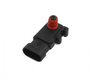
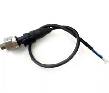
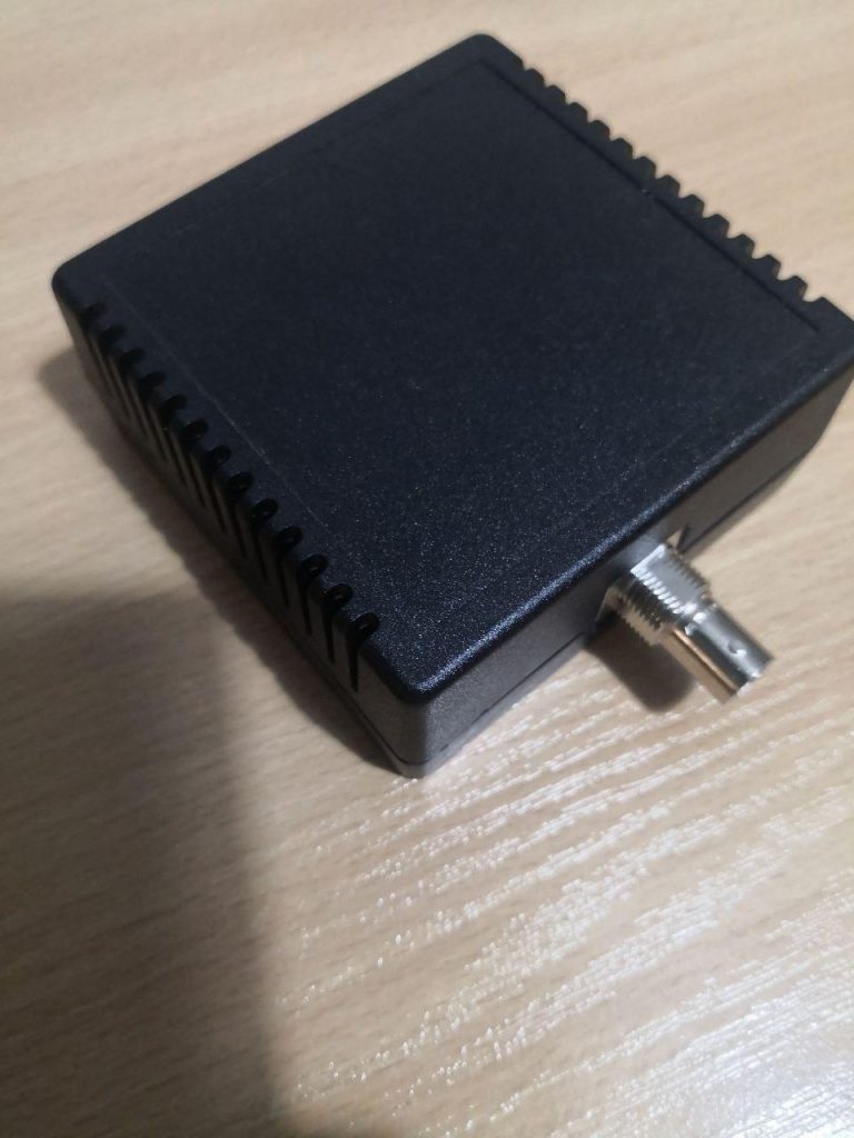
Vacuum Transducer
Interface and usage of a Vacuum Transducer with HScope for real-time pression measurements.
Applications
Interface and usage of a Vacuum Transducer with HScope for real-time pression measurements.
 Applications
Make your own DIY In-Cylinder Pressure Transducer for real-time analysis with HScope.
 News
News
The cursors can be locked so once positioned they can be moved together.
LIN decoder now integrate better stats and data report. Data can be exported.
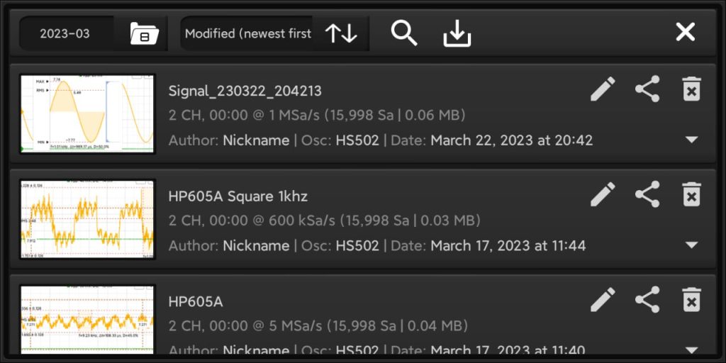
You can search waveform by keywords.
 Oscilloscopes
Subscribe to the following newsletters to vote and receive news on your favourite oscilloscope!
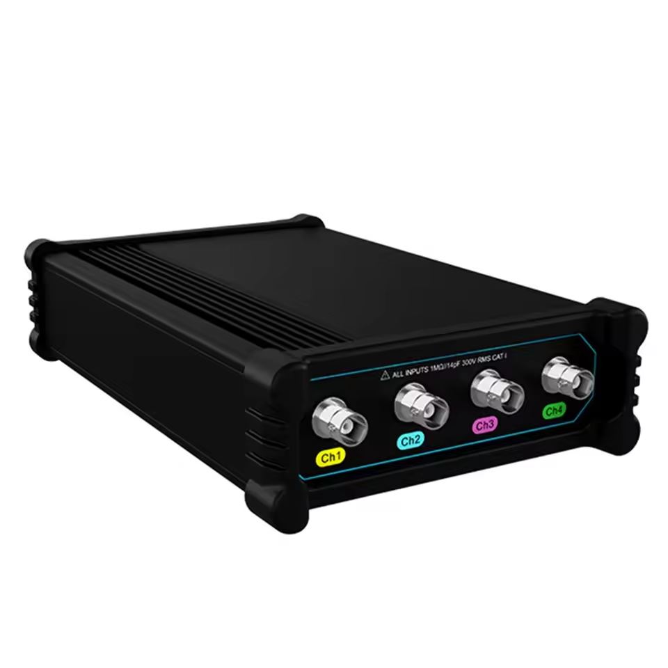
Subscribe to Micsig VTO2004 mailing list:
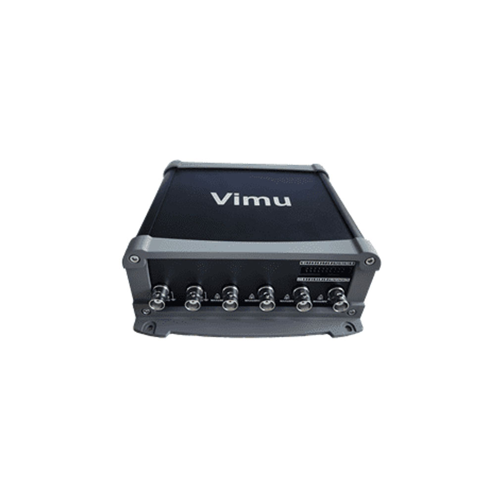
Subscribe to Vimu MSO41 mailing list:
Subscribe to DSCope U2P20 mailing list:
HS10X
I hope you did not have to read this content. It means something went wrong. Be armed with patience and good luck! 🙂
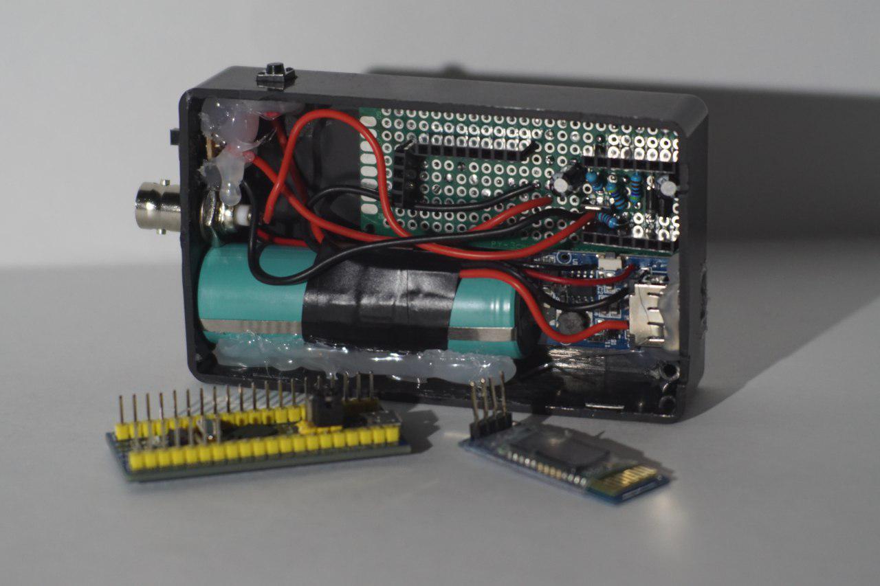
Major issue of this project is in the HC-05 or HC-06 module sourcing. The market is full of different PCB versions with different firmware versions, working with different commands and with different specifications.
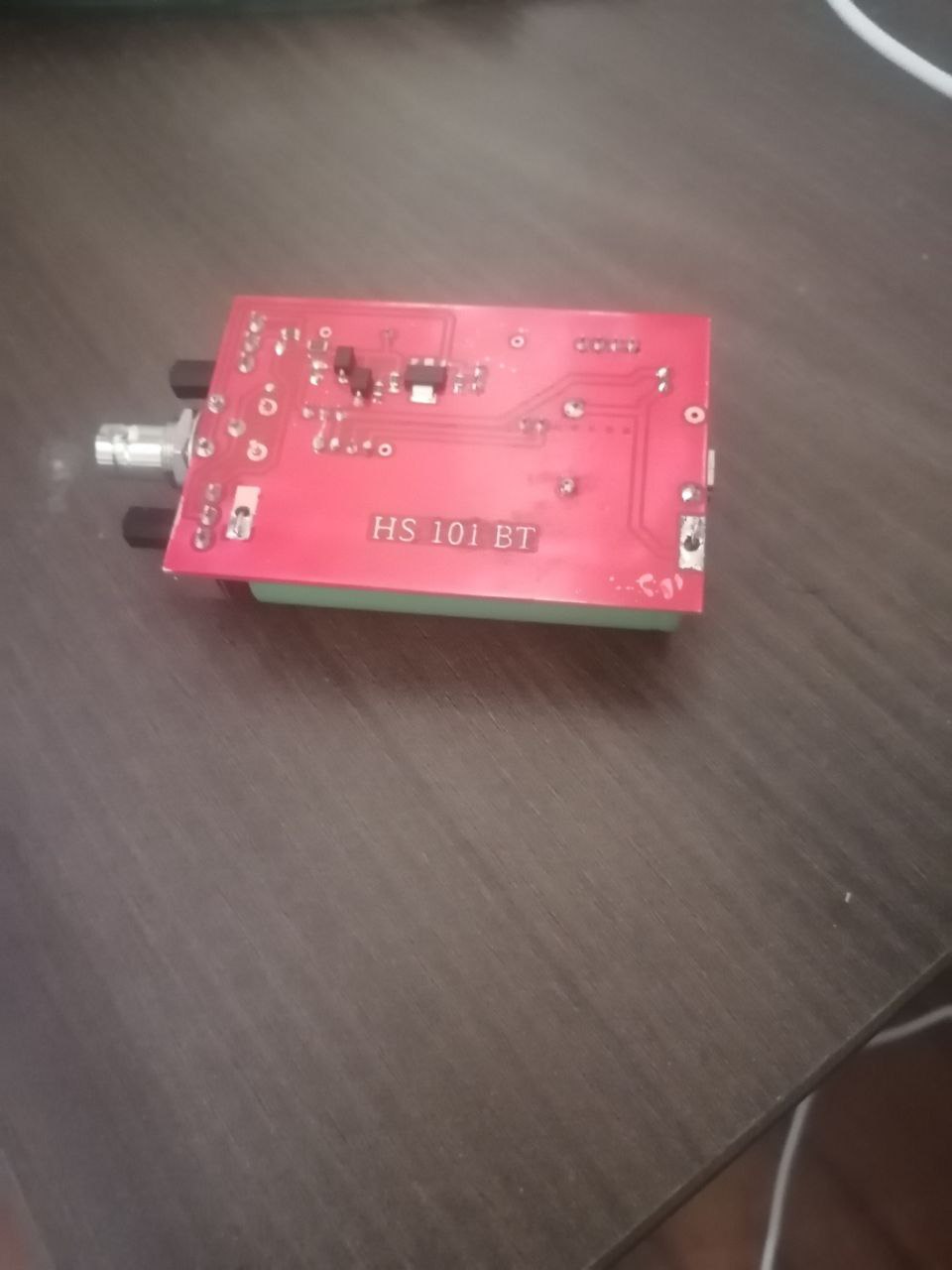
Due to high variety of HC-05 and HC-06 BTL modules in the market, we strongly suggest to purchase it here to have a working hardware already configured for HS101 BLT Oscilloscope.
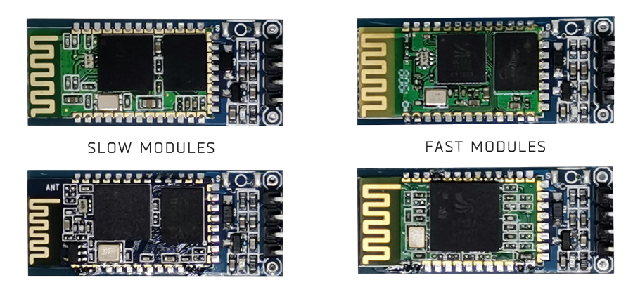
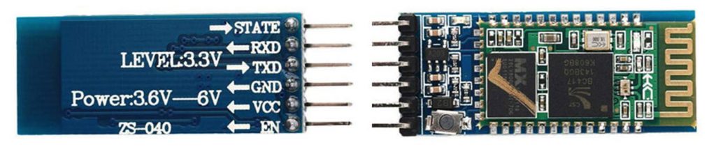
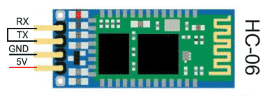
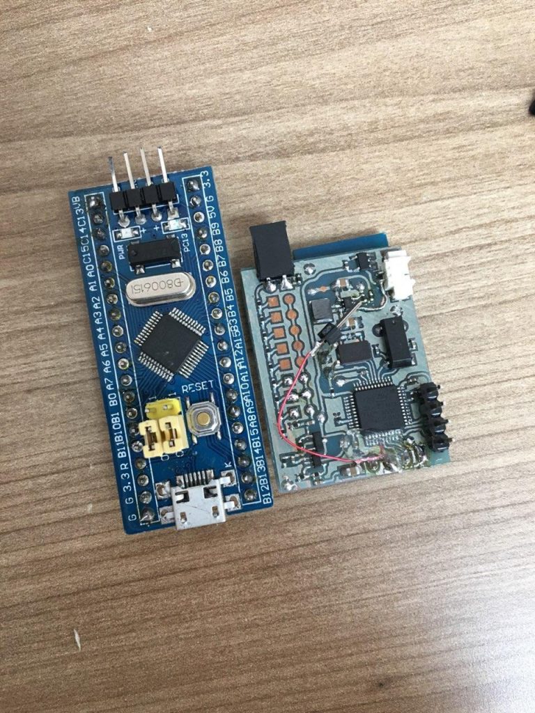
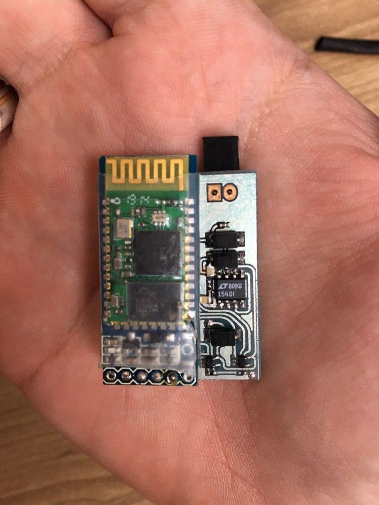
Following are the modules that are not good for this project since max speed is limited to 115200. You may know that are wrong modules because they use a small chip compared to the fast ones (see pictures below).
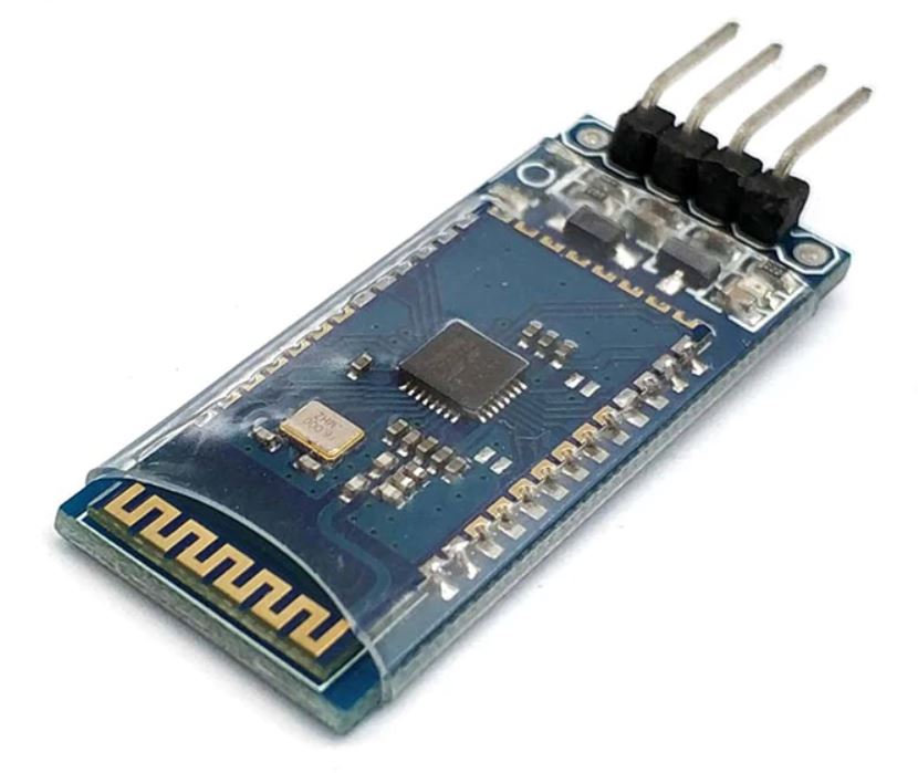
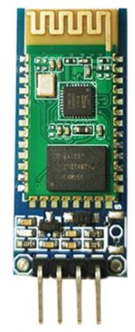
Are those usually with 4 pins and no button. They may install the firmware with HC-06 protocol and the firmware with HC-05 protocol. In the second case you have a very fast module (it can send data up to 20-25fps in HScope).
HS101 Bluetooth Firmware in the STM32 allow the setup procedure to work with both HC-06 and HC-05 protocols.
Since Firmware v.10.1 you can configure the HC-05 module with the Wire Setup procedure but before powering on the STM32 and HC-05 you must keep pressed the button on the HC-05 (this will allow the module to enter in AT mode).
You can see the result on the Debug serial port (pin PB10 of STM32, baud rate: 115200).
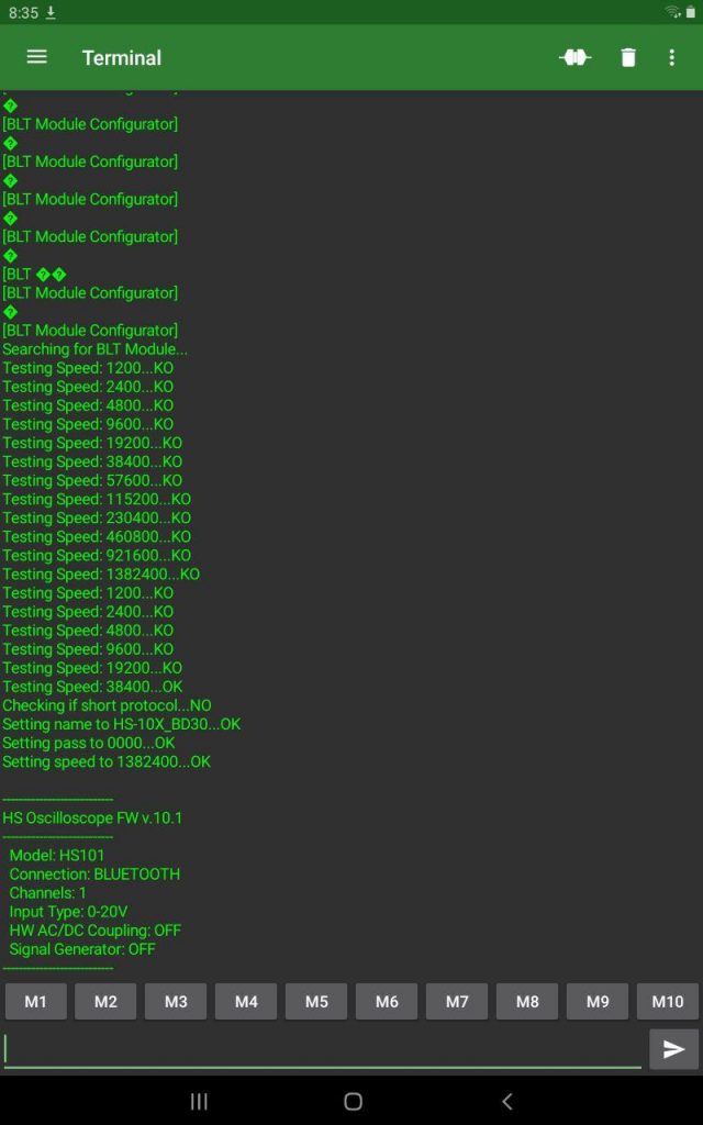
If the automatic configuration doesn’t work here is the manual procedure.
It has been reported that some module cannot communicate at 1.3Mbaud. Some modules won’t allow configuration of serial port to 1382400 baud, other modules just stop to communicate after they get this configuration.
You have configured the Bluetooth Module to work at 1.3Mbaud. Now shortcut RXD and TXD of the HC-06 Module and with this app (Serial Bluetooth Terminal) check if the commands you send echoes back.
However you still don’t know if the serial port is communicating at 1.3Mbaud or less (when you configured the serial speed it is possible that the AT command reply OK but actually the module did not apply the requested speed)
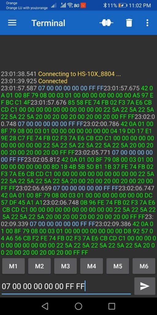
Connect the Bluetooth Module to the STM32, then use the app Serial Bluetooth Terminal to talk directly to the Bluetooth Module. Following are the configurations for this app.
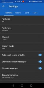
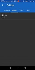
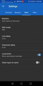
Sent the following HEX string to the Bluetooth Module: 07 00 00 00 00 00 FF FF. If the Bluetooth Module can communicate with the STM at 1.3Mbaud then you should receive a reply:
Has been reported that with some phone Hscope cannot see the Bluetooth module. Here the list of phones with issues:
 News
News
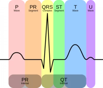
In this project, we will interface AD8232 ECG Sensor with HS101 Oscilloscope (based on STM32 bluepill board) and observe the ECG signal on HScope.
Read more “ECG with STM32 and AD8232”
HScope
Here are the new features developed in 2023/2024 (users with the last license purchase before 2023 can activate these features through the Update 2023/2024 in the License panel).
Time unit can be set in Automotive Mode.
Duty function allows to detect variation in the duty cycle of an input waveform and so to find sudden variations or possible issues.
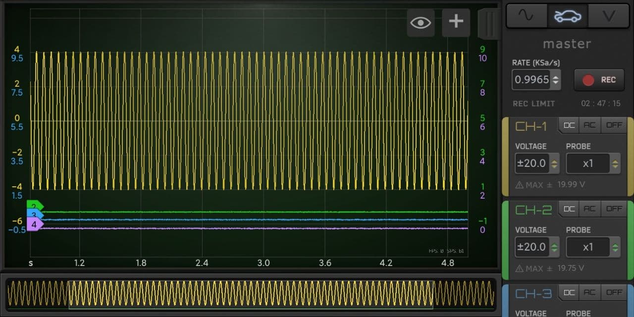
Possibility to record at oscilloscope high rates in Automotive mode, with paging mode.
FFT data can be exported in CSV format.
HScope
Here are the new features developed in 2022/2023 (users with the last license purchase before 2022 can activate these features through the Update 2022/2023 in the License panel).
It is possible to assign custom names to the channels. These names will be saved when the waveform will be saved, and also will be exported in the Report.
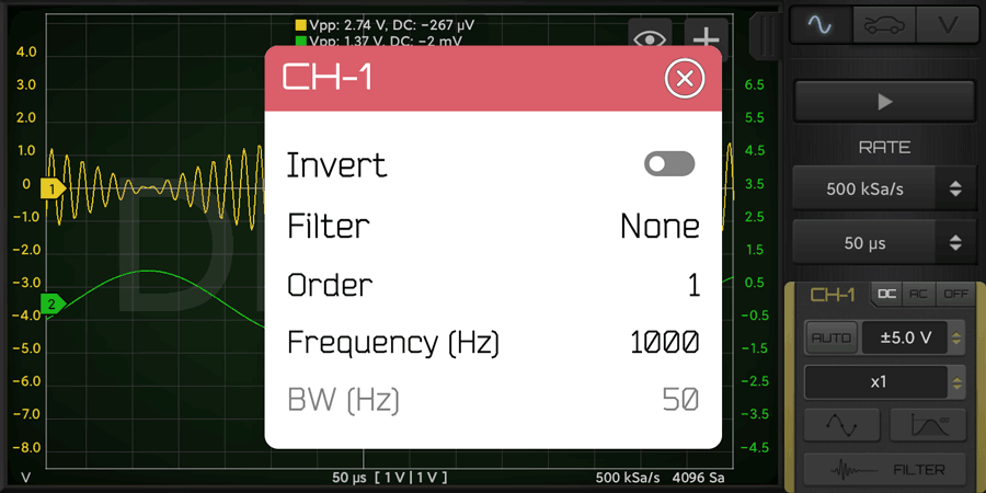
Channels signal can be inverted with the Filters.
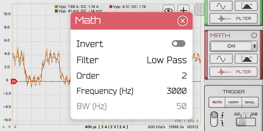
Can apply post-processing filters to the Math Channel.
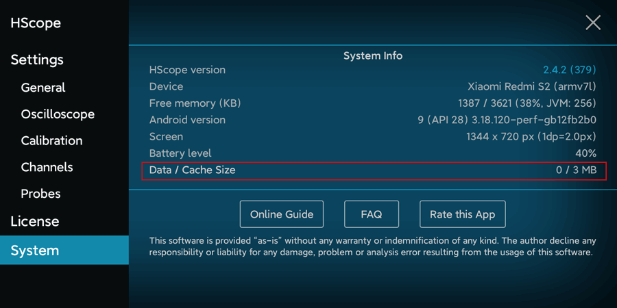
Better Cache Management to keep disk usage controlled. It is possible also to clear the cache in HScope Settings (System tab) – suggested for updates from old versions of HScope.
 News
News
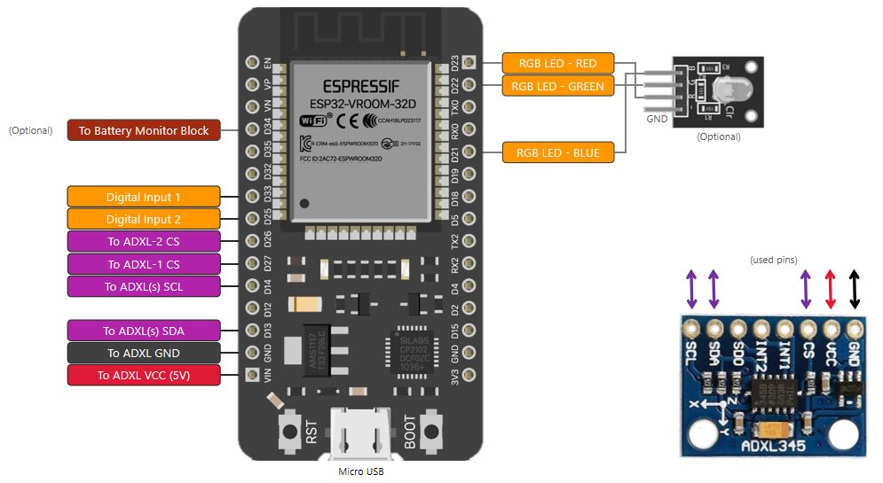
| Sensor 1 (ADXL345) Pin | ESP32 Pin |
|---|---|
| GND | GND |
| VCC | VIN (5V) |
| CS | D27 (IO27 or GPIO27) |
| SDA | D13 (IO13 or GPIO13) |
| SCL | D14 (IO14 or GPIO14) |
| Sensor 2 (ADXL345) Pin | ESP32 Pin |
|---|---|
| GND | GND |
| VCC | VIN (5V) |
| CS | D26 (IO26 or GPIO26) |
| SDA | D13 (IO13 or GPIO13) |
| SCL | D14 (IO14 or GPIO14) |
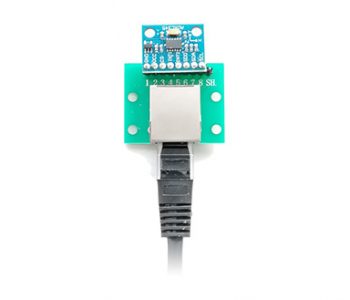
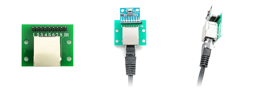
In case you need to use long wires for the sensors, it is suggested to use Ethernet cables for the connections. In addition you can use also a RJ45 Breakout Board as the following:
You can also build this device with the PCB you will find here which include:
HScope
Here are the new features developed in 2020/2021 (users with the last license purchase before 2020 can activate these features through the Update 2020/2021 in the License panel).
Histograms are graphical representations of data which divides it into intervals or bins. These intervals/bins are plotted on a bar chart such that the bar height relates to the number of data points inside each interval/bin as a function of the data value.
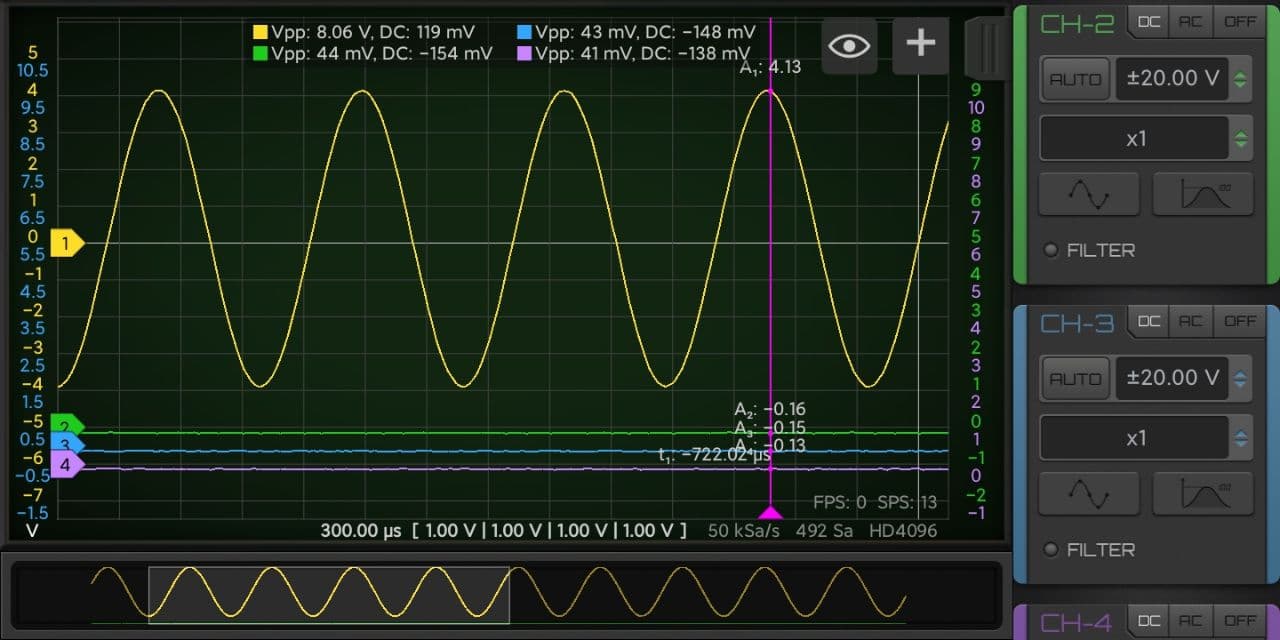
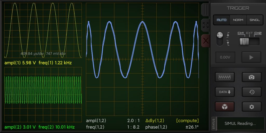
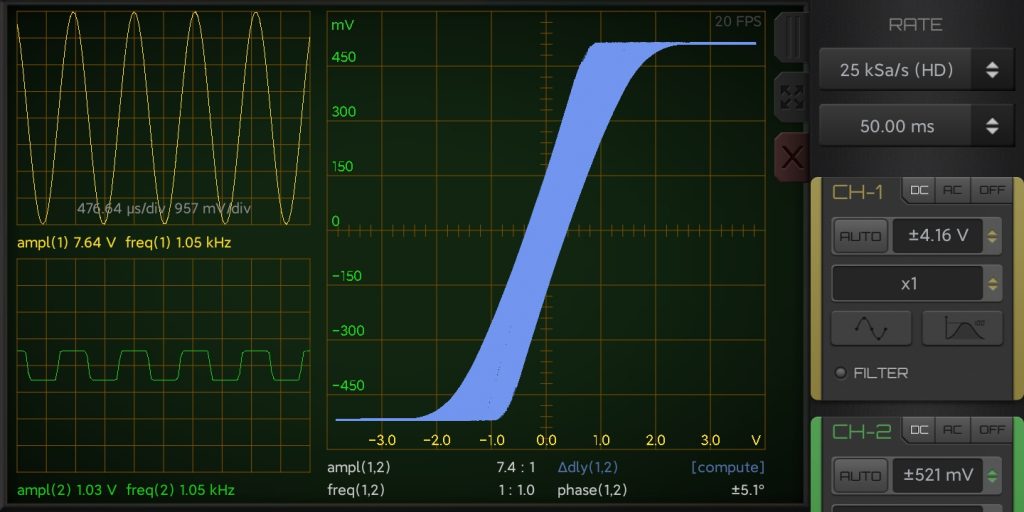
The following screenshots shows a series of typical waveforms, withthe associated histograms of the sample values in the blue bar graph.
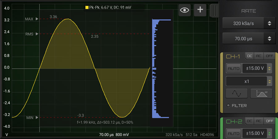
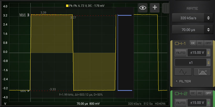
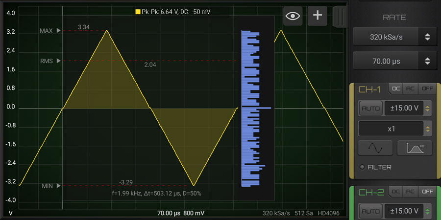
The histogram gives us an approximation of the probability density function (pdf) of a set of values. The shape of the pdf tells us about the underlying process. In the case of the sine wave, remember that the rate of change of the sine is maximum at the zero crossings and minimum at the positive and negative peaks. When we sample the waveform uniformly, we get more samples at the peaks and much fewer at the zero crossings. This is due to the differences in the rate of change, thus explaining the shape of the histogram. For the case of the triangle wave, the rate of change is constant, so samples are taken evenly. This results in what is called a uniform distribution.
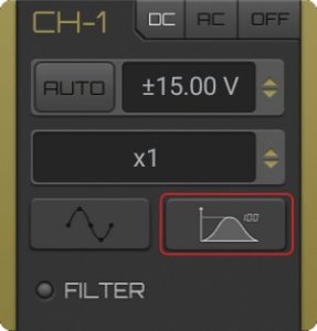
Press the stats button in the channel of interest until the Histogram chart appear.
This module allow to use the output calibration pin (generally set to 1KHz square wave) to generate a PWM output signal. Max frequency and duty cycle range depends on the device (detail are in each oscilloscope page).
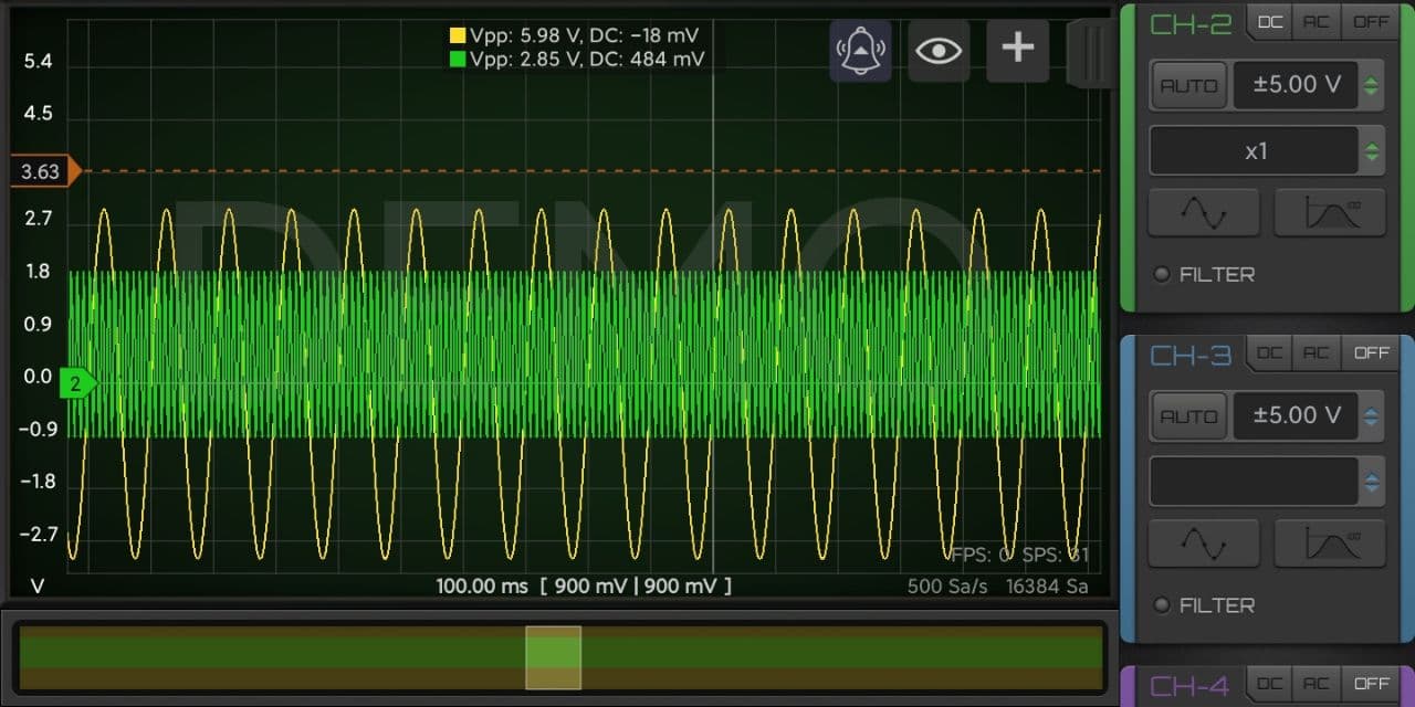
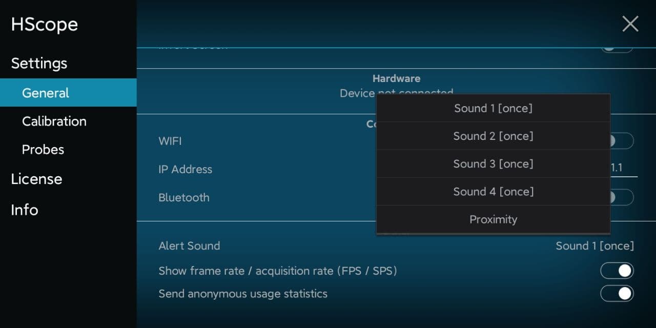
Horizontal cursors can be alarmed to produce a sound when the signal goes over or under the cursor level. When you select an horizontal cursor you can see the bell icon on the top and click it to select the kind of alarm (over / below / off).
In the settings you can select the alert sound kind.
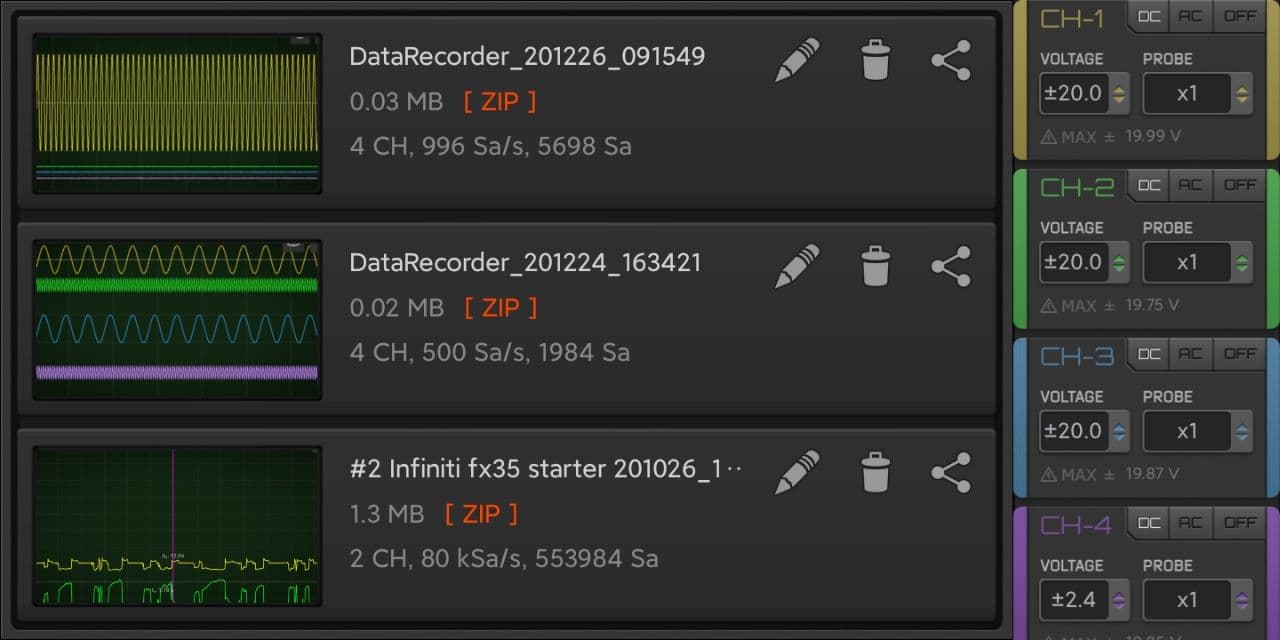
4 Channels support for Import/Export files. Currently only Hantek 1008 support 4 channels acquisition.
 How To
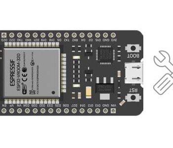
How to repair an ESP32 development board (common cases).
Read more “Repairing ESP32”
HS10X
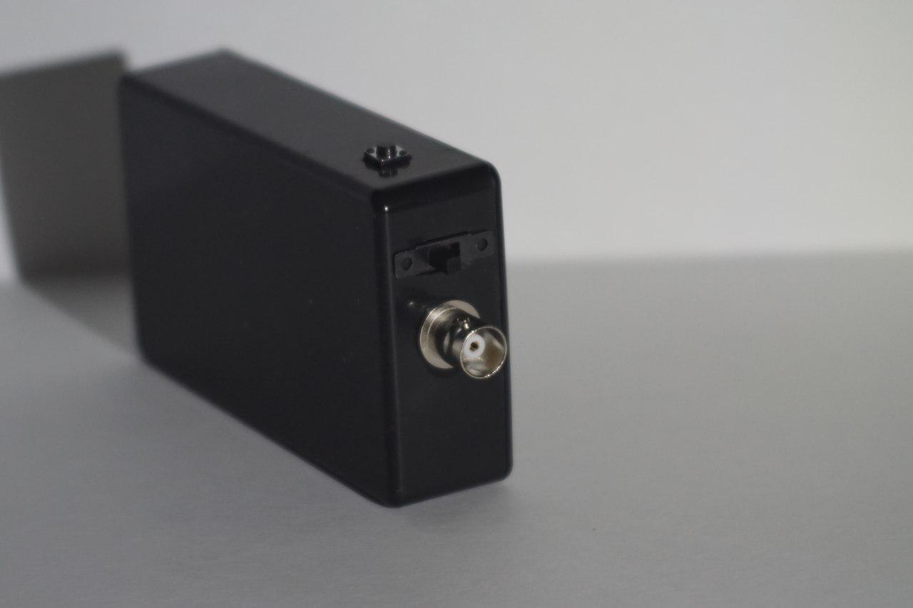
You can build a battery powered, portable 1 Channel oscilloscope with this variant of the HS101 DIY Oscilloscope (based on STM32F103 Blue Pill). It has the lowest noise among the HS101 variants. It can be implemented with several input ranges and uses HScope Android app.
This project is difficult to build due to the different HC-06 Bluetooth modules sold in the market. Under you can find the link where to buy a Bluetooth Module suiteable and already configured for this project.
Warning: Phones should have at least Bluetooth V.4.0 to work at highest speed with HC-06 Bluetooth Module.
| Channels | 1 |
| Input Range | (according the implemented input stage) |
| Sampling Rate / Bandwidth | (according the implemented input stage) |
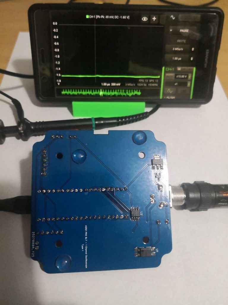
| Input Noise | < 0.08% noise @ 900KSa/s (<0.03% @ 100KSa/s, test results with the Black Pill) |
| Samples | 1024 (each scan) |
| Input Impedance | (according the implemented input stage, 10kOhm or 1MOhm) |
| Modules Supported | Automotive Module @ 10 KSa/s |
| Working Range | Without any boxing, the connection has been tested to works at full speed up to 4m distance. |
You need just an HC-05 or HC-06 Bluetooth module to transform an HS101 Oscilloscope into Bluetooth oscilloscope.
Due to high variety of HC-05 and HC-06 BTL modules in the market, we strongly suggest to purchase it here to have a correct hardware to make this device.
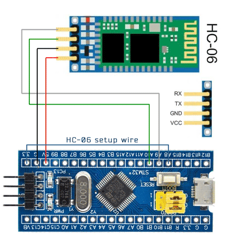
Full schematic of HS101 Bluetooth PRO is available on EasyEDA. Following is the connection for the HC-06 Bluetooth module (for the HC-05 Module connect to B15 instead of A8).
1. Flash the STM32 with the specific Firmware for Bluetooth. Firmware is available on STM32Utils flashing utility.
The HS101 BLT firmware in the STM32 has a procedure to configure the HC-05/06 module at the first time.
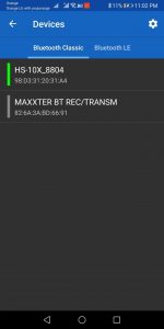
Setup Wire. If you suspect you have an HC-06 Module connect the setup wire to pin A8. For HC-05 Module connect it to pin B15.Setup Wire, assemble the analog part and power on. On phone search for the bluetooth devices and pair the device called HS10X-XXXX with password 0000 (first time it may require some time for the phone to show the bluetooth name). Pairing is required just at the first time.After the bluetooth has been paired with the phone, just open HScope app, be sure that:
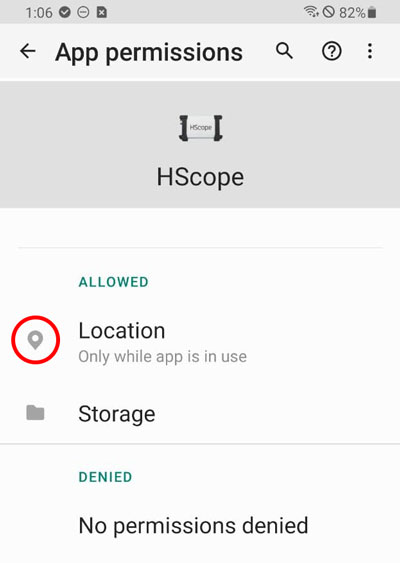
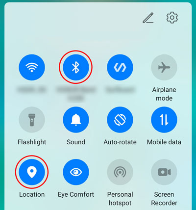
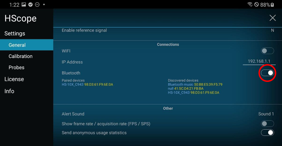
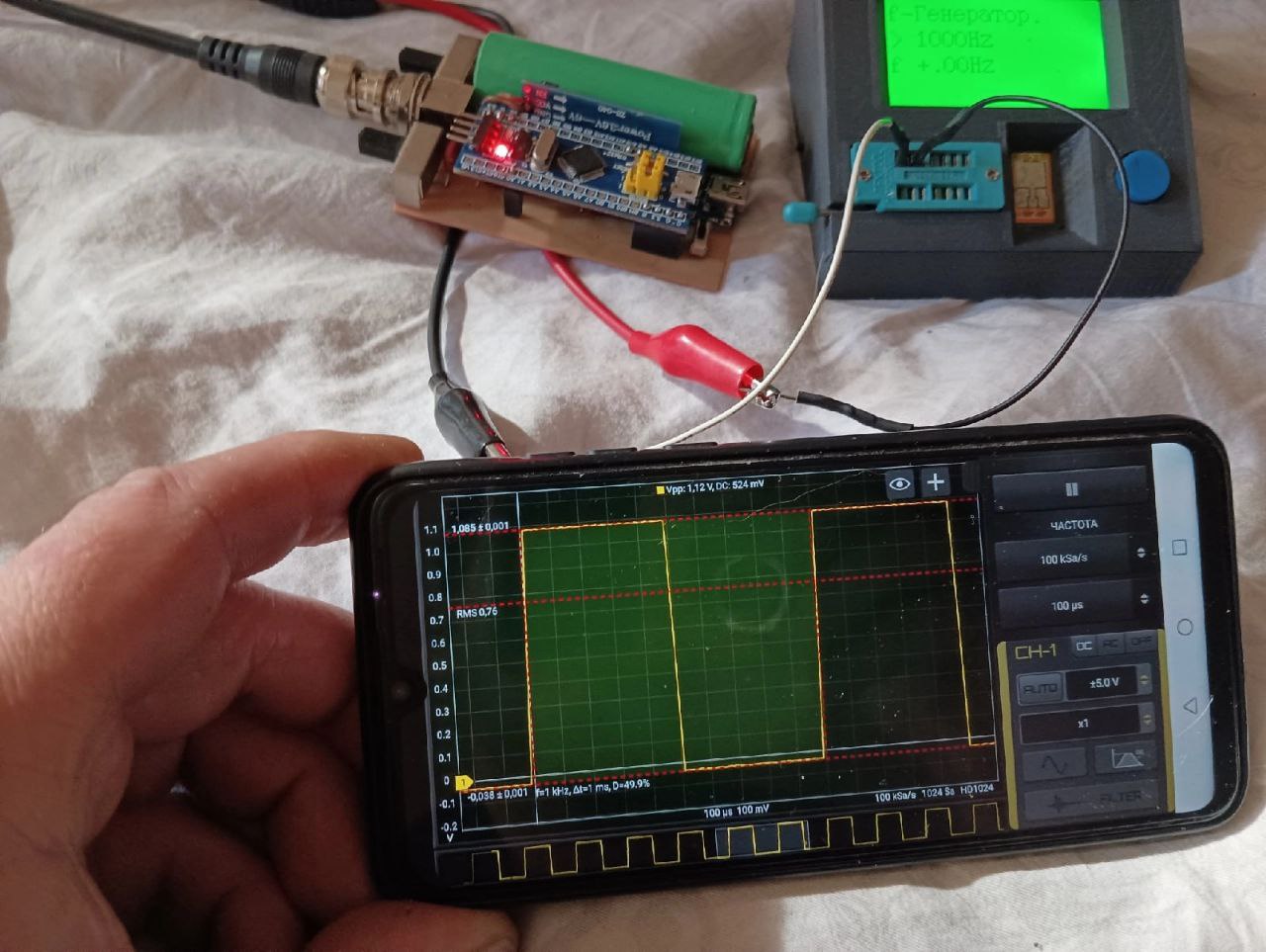
HScope should detect the bluetooth oscilloscope automatically and start to show the signal.
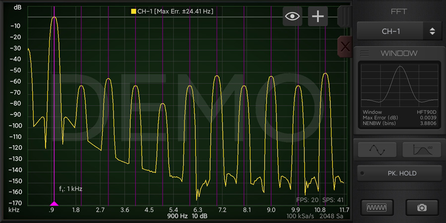
– Refresh rate: 7-12 FPS (20-25 FPS with some Bluetooth Module, see under)
– No. samples each scan: 1024
– Real time continous acquisition: 10KSa/sNote: Reat time continous acquisition is critical to get with Bluetooth. It has been found that some phone could have issue with Bluetooth fast communication, this create corruption of data. To verify if your device has this issue enable FPS/SPS visualization. It should show always 9-10FPS for rates equal or less than 10KSa/s.
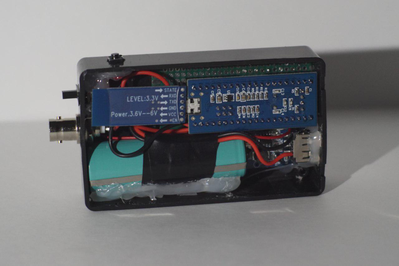
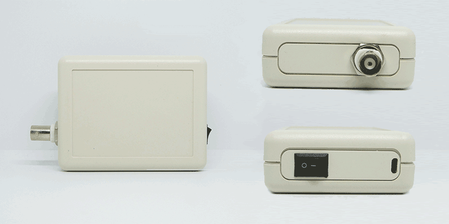
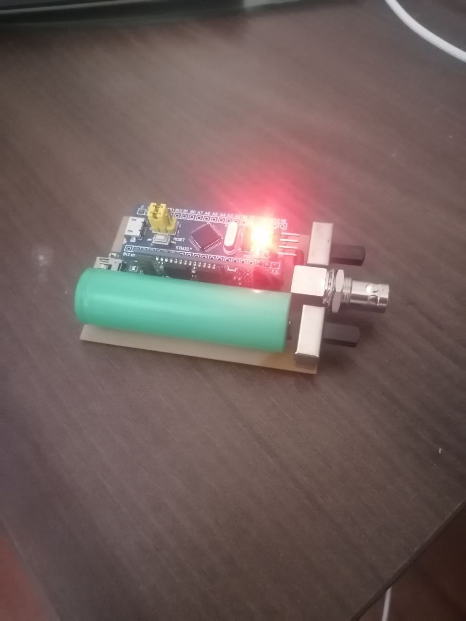
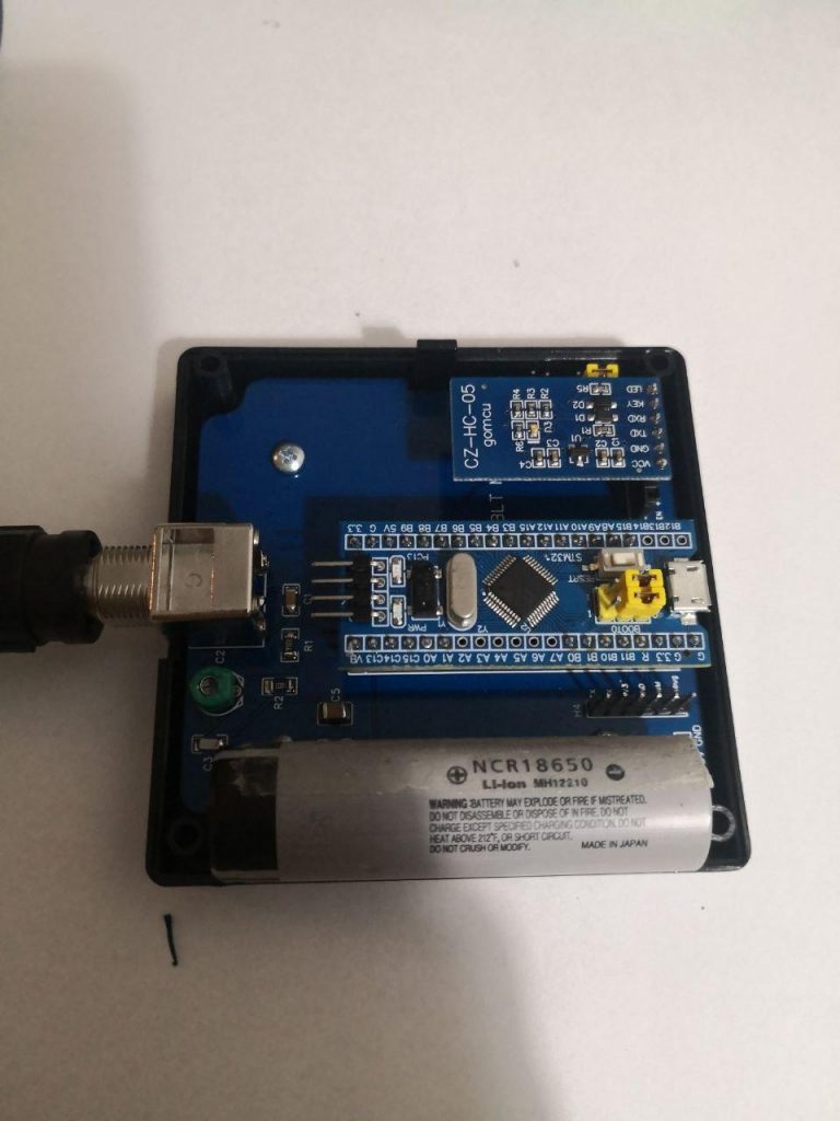
You can use the HS101 Bluetooth with a standard USB battery pack connected to the micro-USB or you can implement your own power with one 3.7V Lithium battery and a small battery charger with 5V UPS circuit like here.
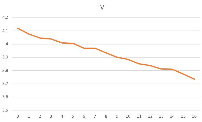
In case you use a 18650 type battery you can connect it directly to the 5V pin since it maximum voltage is around 4.2V. Tests on this kind of battery (2000mA capacity) with HS101 PRO showed continous bluetooth transmission up to 16 hours without problems (see graph on the right). When the battery voltage is around 3.6V some noise start to show up in the acquired data but the bluetooth comunication does not get interrupted.
It has been found that no additional noise is generated by the bluetooth module. Bluetooth + Battery configuration provide less overall noise than the standard USB connection.
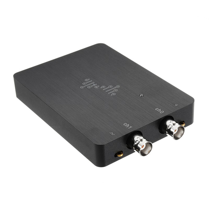
– CAN Bus Dongle
– Relative Compression Test Dongle
Built by Андрюха (2022)
Built by Bruno (2020)
Built by Mikael (2020)
Built by Denis (2019)