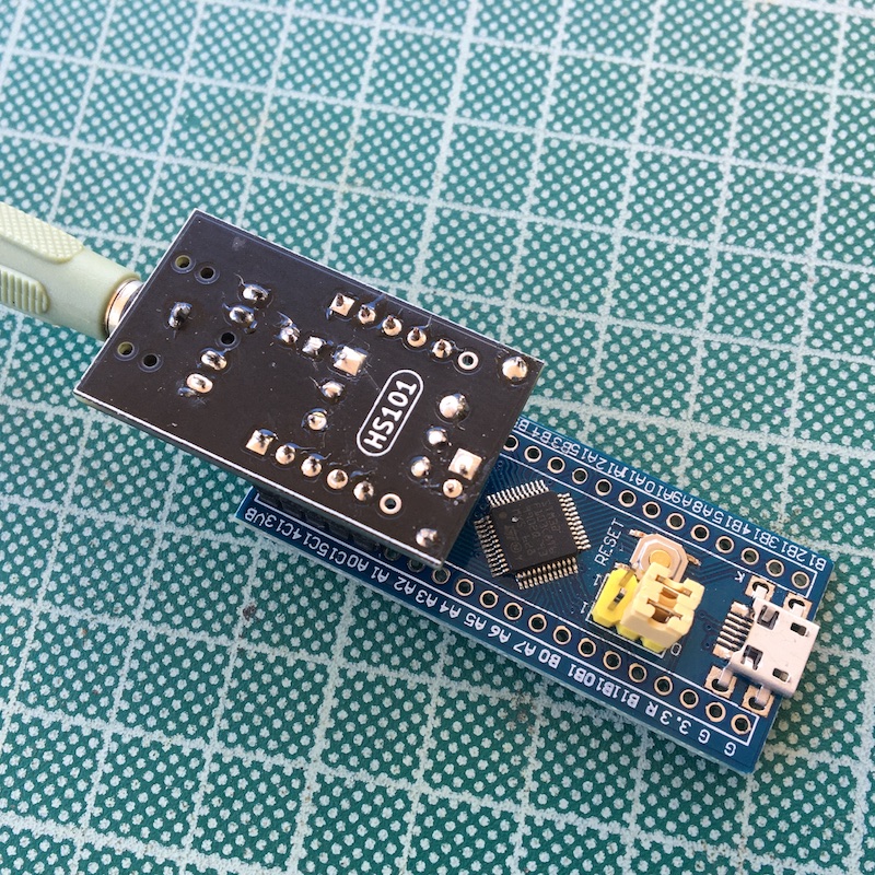
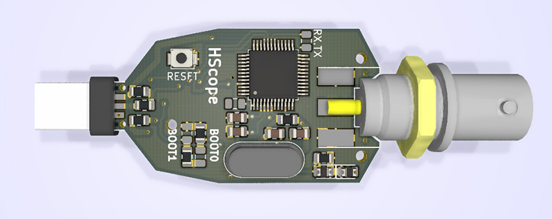
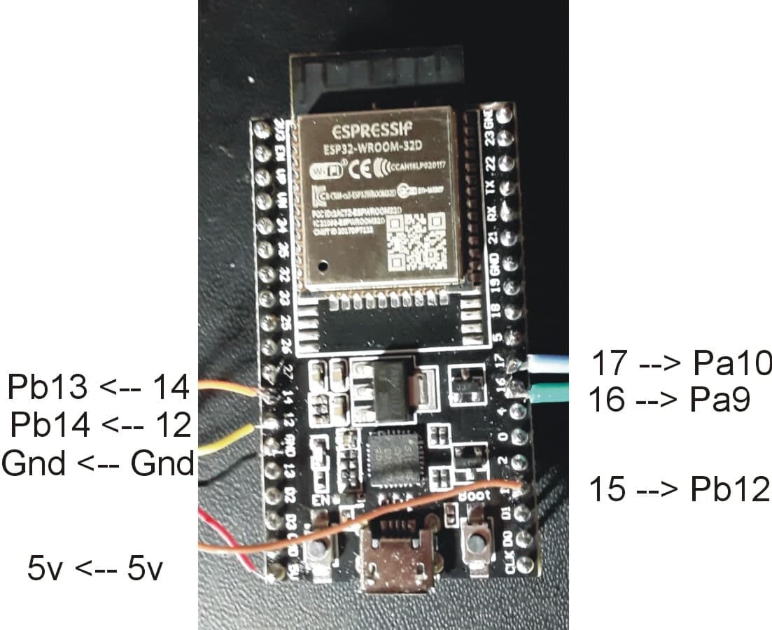
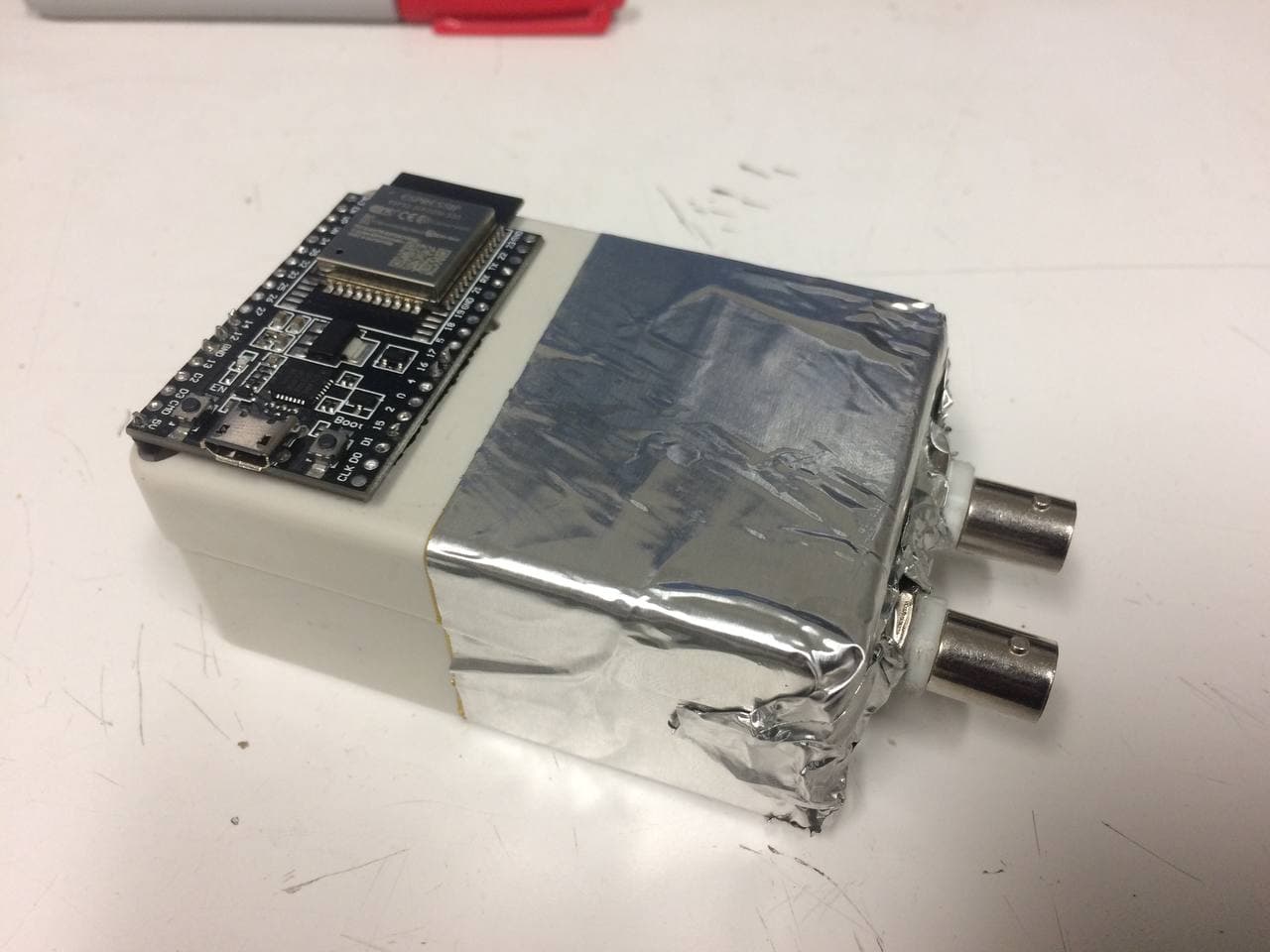
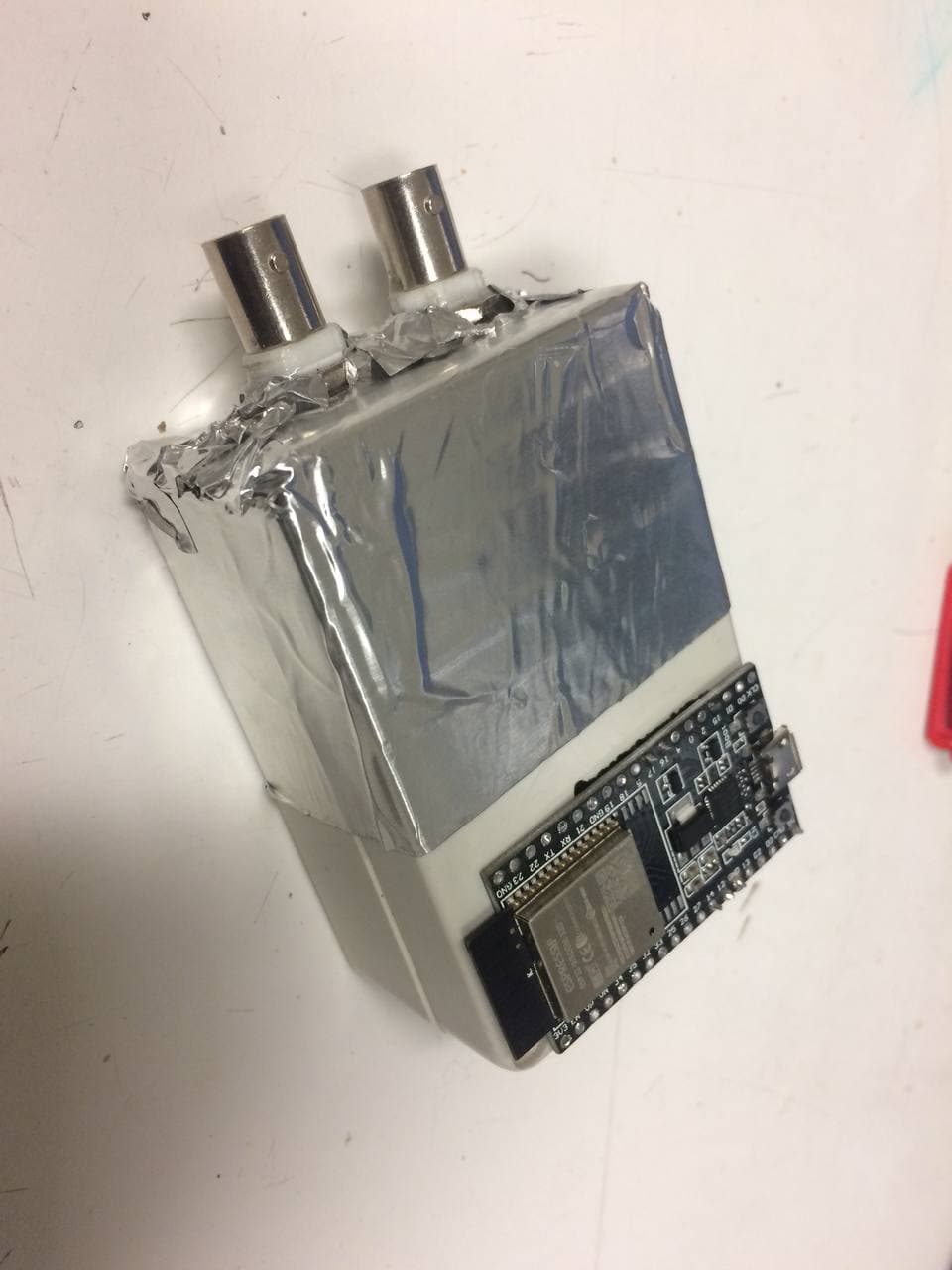
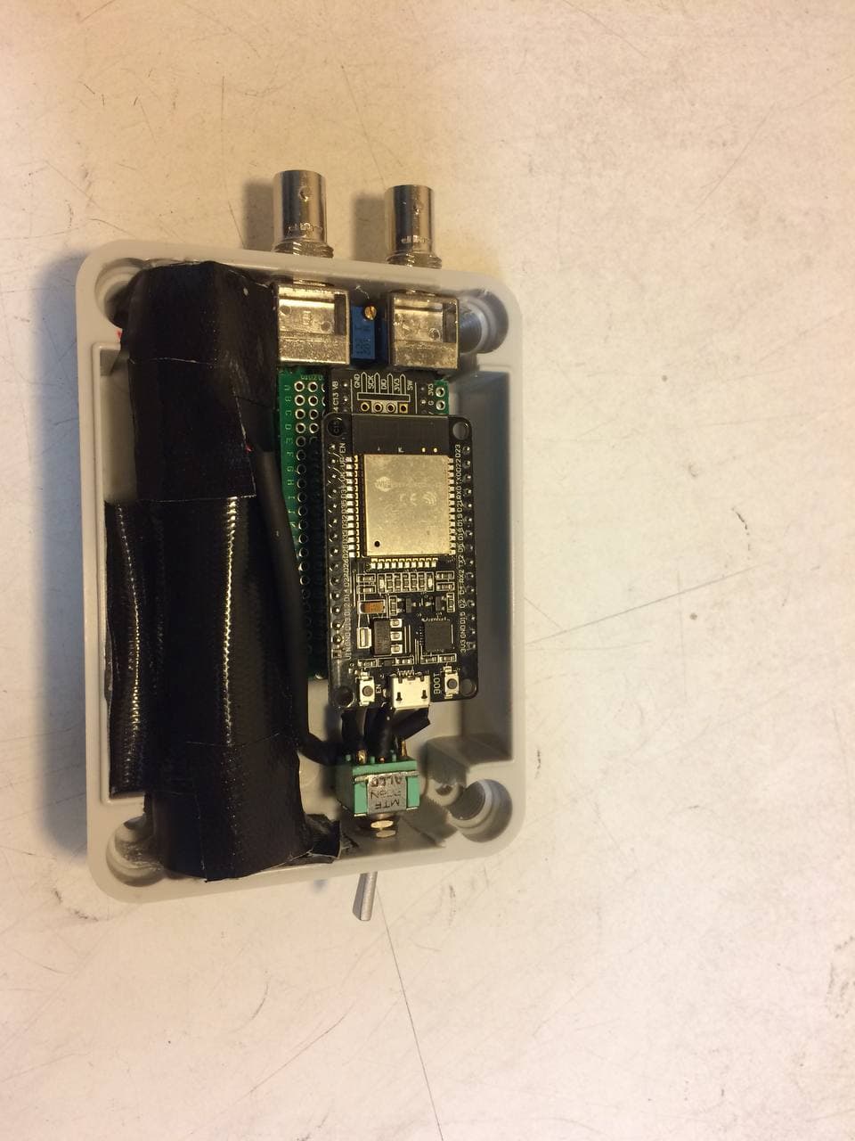
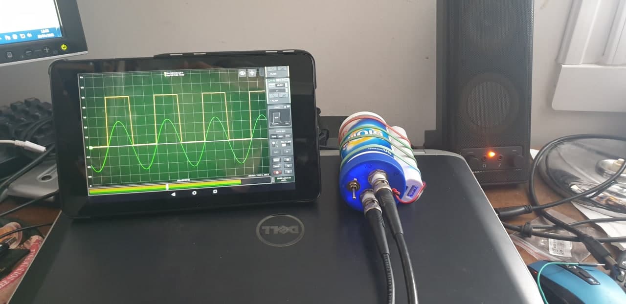
Blog

HScope

Change Log

Known Issues

  • General workaround for issues: delete and reinstall the app.
  • License Activation problems found for some phones.
    Workaround: remove/close the app from Android tasks list and restart the app. Restart the phone and keep internet on the first time to let Google Play to sync the account.
  • Wifi oscilloscope disconnect randomly, also during logging.
    Workaround: disable bluetooth since when some paired device is nearby the Android system stops all the apps, including HScope.

TODO List

  • Advice for low sampling rate respect signal frequency.
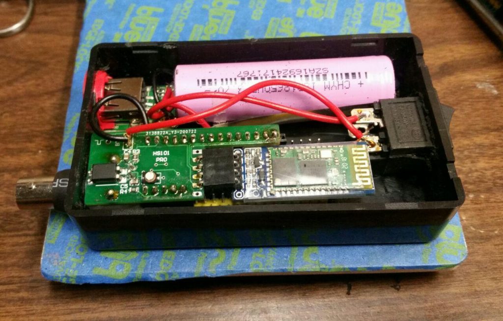
  • Reference signal cannot enabled when HS101 connected by Bluetooth.
  • Add legend to cylinders timing overlay.
  • Enable CH-0 move on Automotive Module
  • Statistics hide away when the signal change –> keep on the screen
  • AUTO option in Rate (change according zoom level)
  • On saved file add information on enabled digital channels

2.4.5 (490) Jun, 2025

Current issues

  • When WiFi is enabled in HScope and no device is connected the file opening crash. Workaround: connect an oscilloscope or disable WiFi in HScope settings.

Improvements

  • New Leak Detector feature (experimental, update 2025)
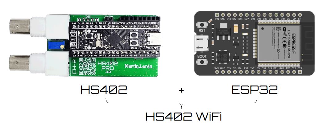
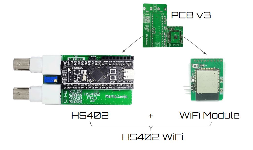
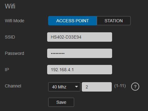
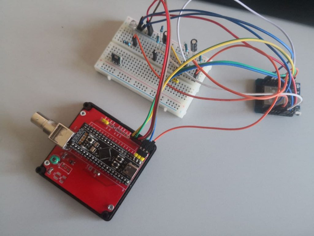
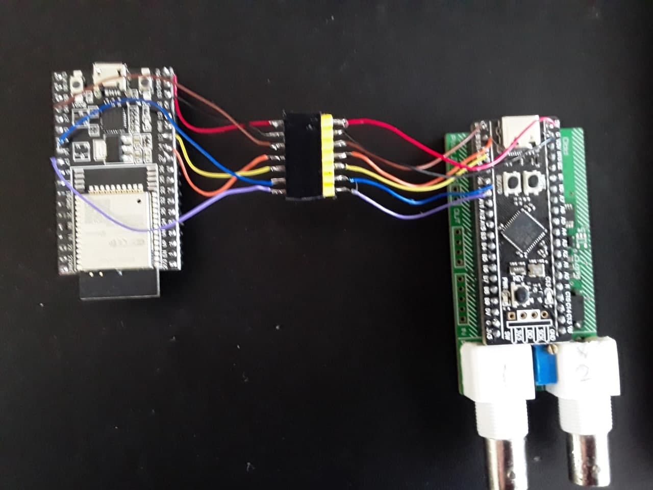
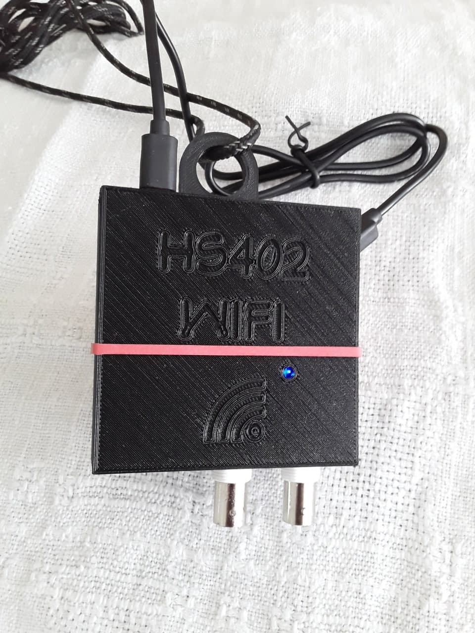
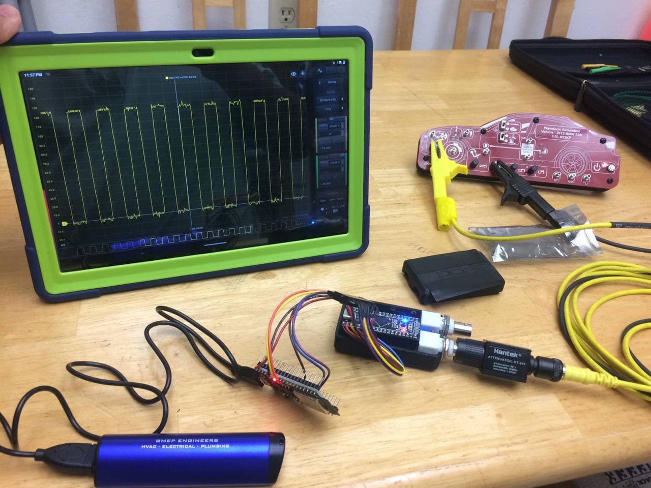
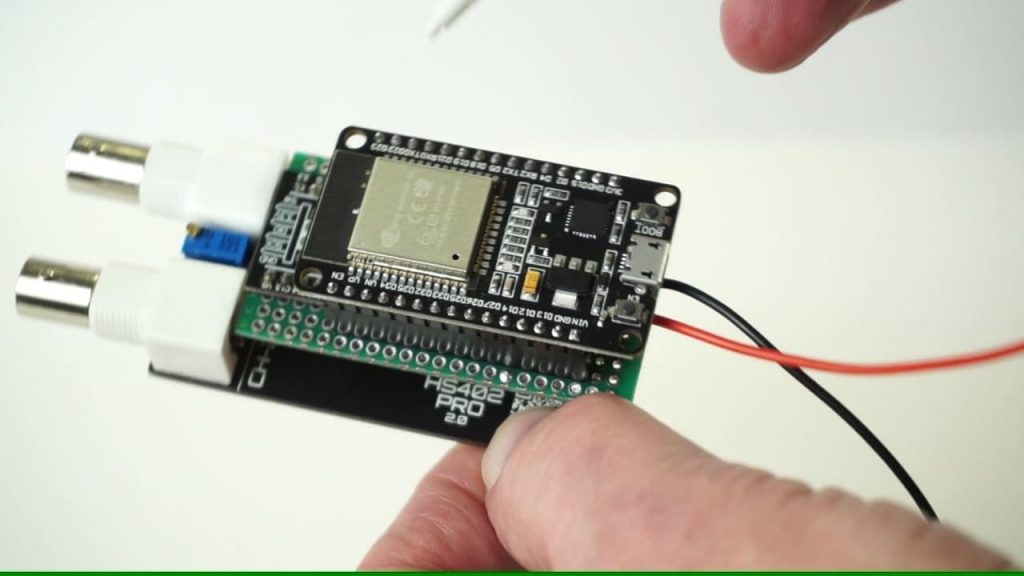
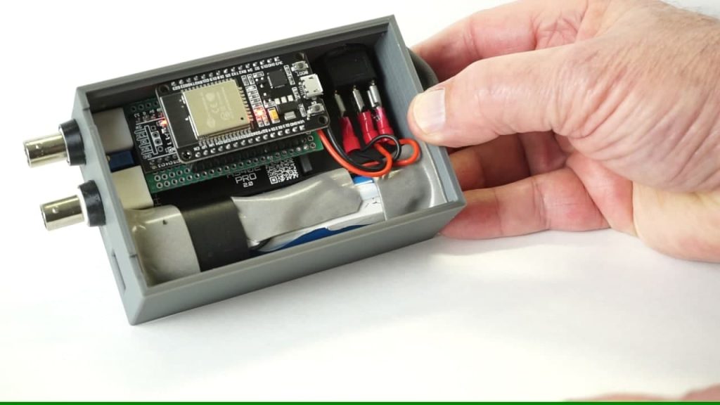
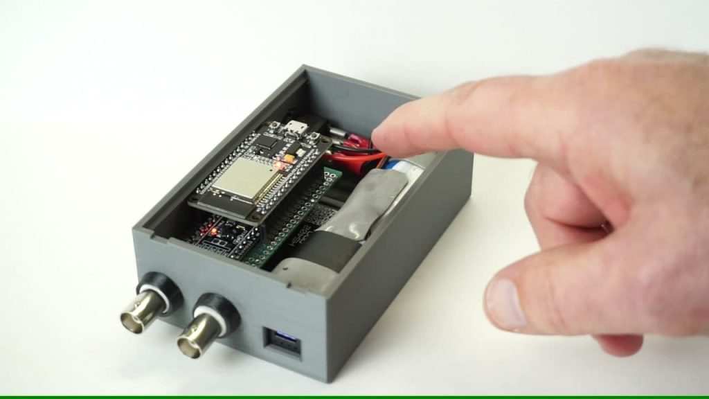
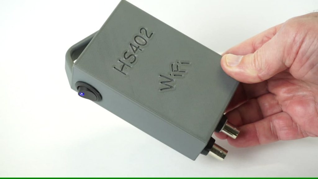
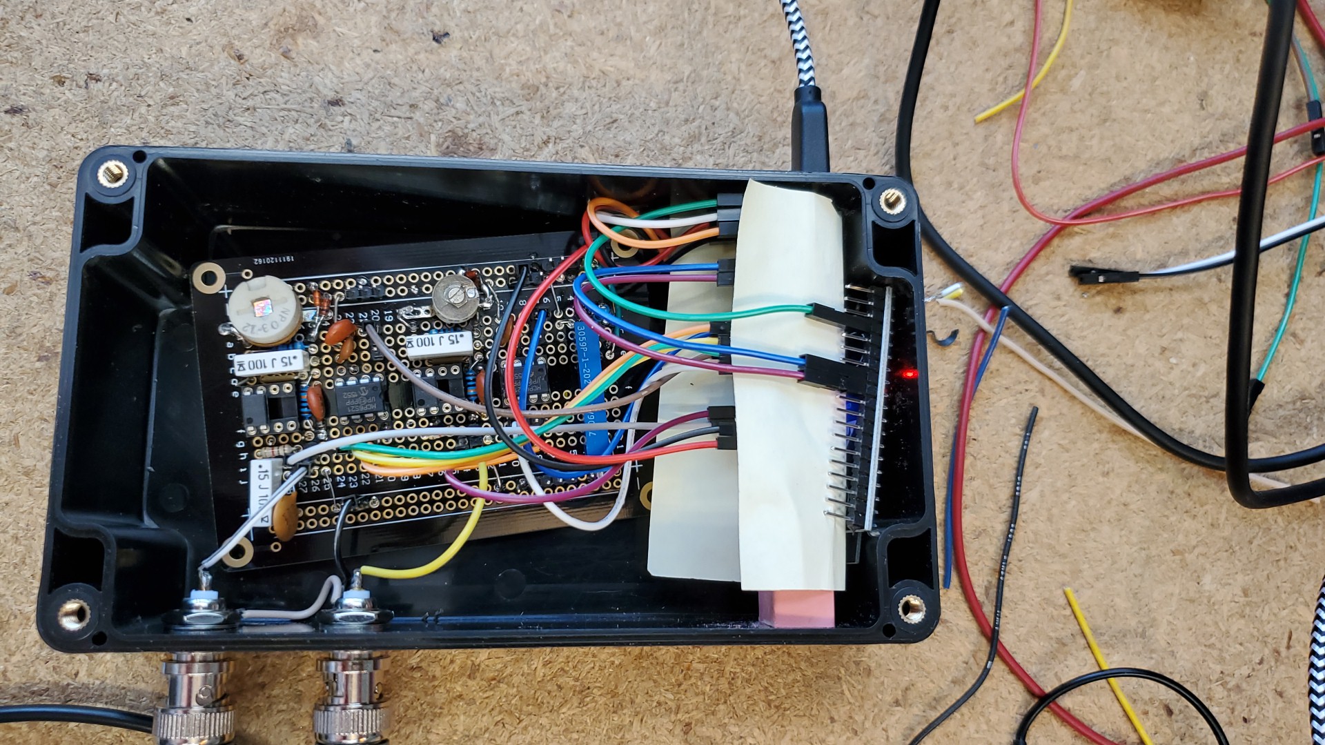
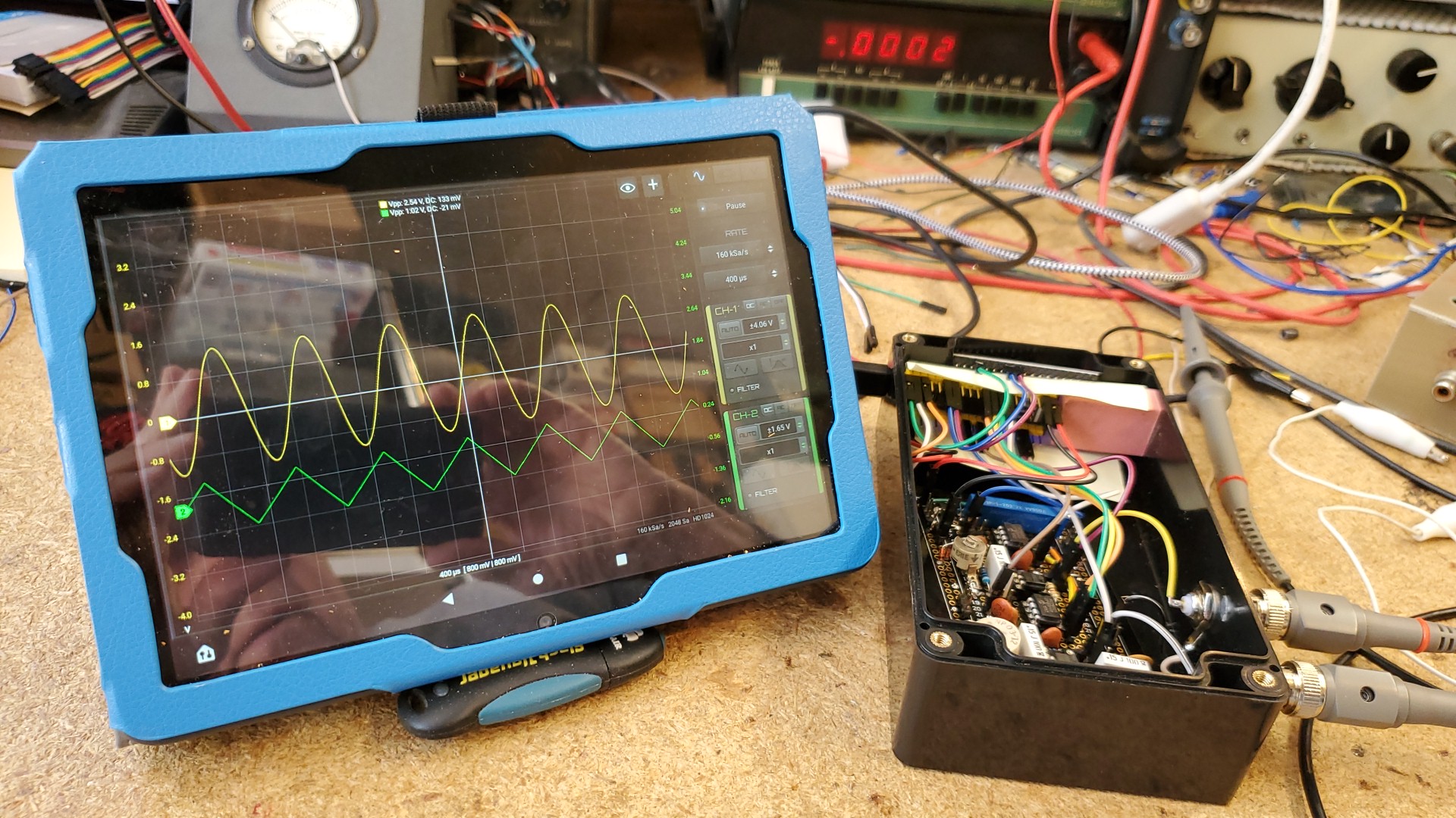
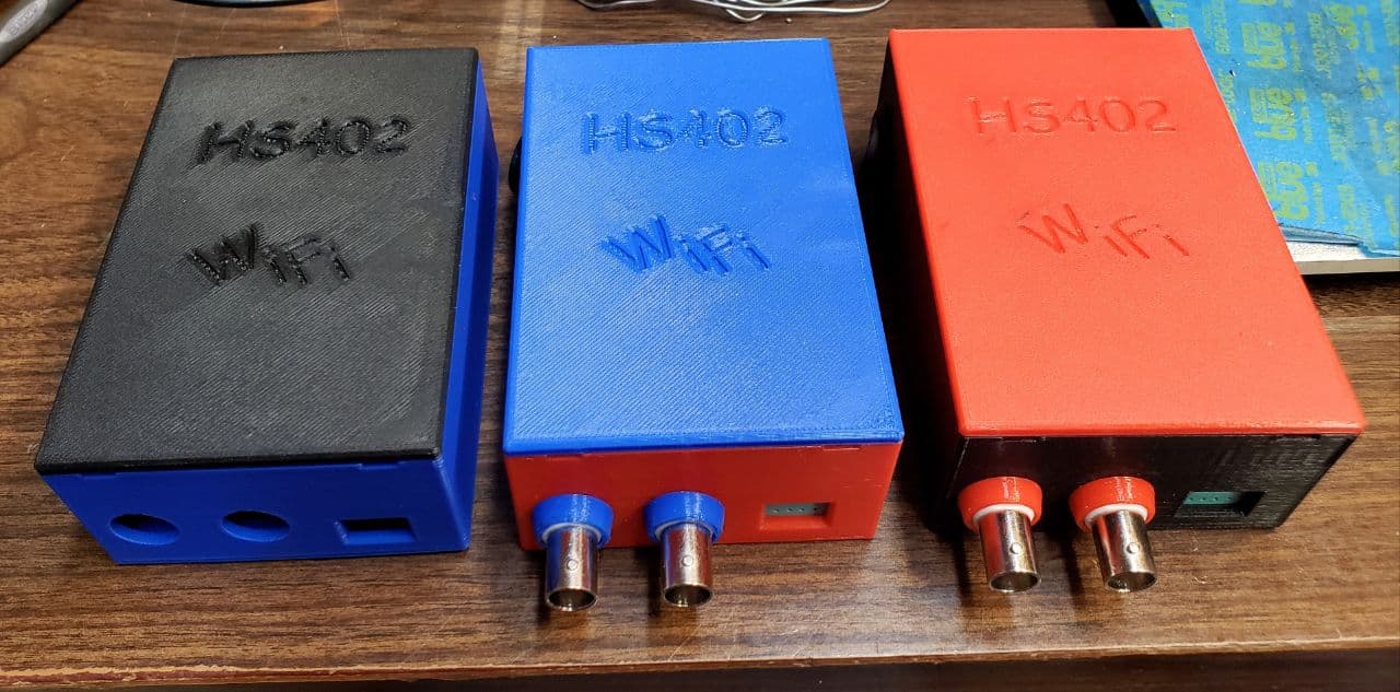
  • HS402 WiFi can connect directly with IP (experimental)
  • FFT auto-adapt signal on screen on Channel change
  • Added sounds (preview)
  • Added Waveforms Search function (update 2025)
  • Update Waveforms management UI
  • Improved Settings page
  • Waveform cursors are placed in the middle of the waveform

Fixed bugs

  • Crash on Bluetooth connection for some device
  • WIT Accelerometer won’t connect in some case (do not need to pair)
  • Fixed sync issues on digital module (oscilloscope mode)
  • Fixed wrong FFT stats for PWM signals in some condition
  • Fixed FFT reset to Channel-1 when stop/start acquisition

2.4.5 (483) Mar, 2025

Current issues

Improvements

  • Added fast button to scroll up the list of waveforms
  • CAN Decoder supports J1939 Layer decoding and Decimal/HEX format, report export in Excel format (Update 2025)
  • Improved LIN Decoder, skip frames between pages, better report, Decimal/HEX format (Update 2025)
  • Added Korean language

Fixed bugs

  • Fast mode switch cause blank screen.
  • Fixed issues on CAN decoder
  • Crash caused by WIT driver for some version of Android
  • Second horizontal cursors could not be moved if taken on the right side
  • Screen gesture freeze in some case

2.4.5 (471) Jan, 2025

Improvements

  • It is possible to see more pictures from the Cloud Waveforms
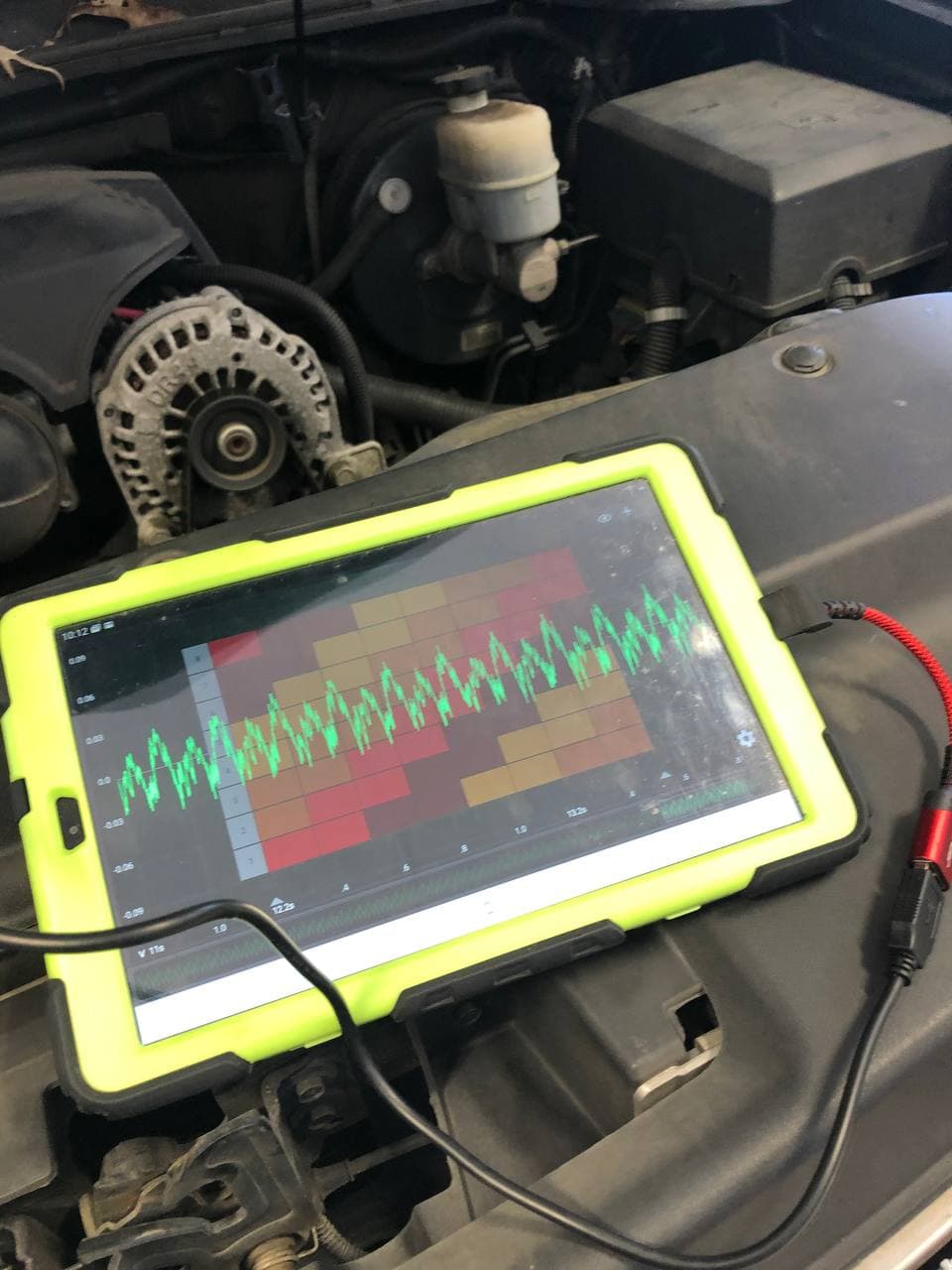
  • Waveform can be cleared in the Automotive Module
  • Improved Master panel in Automotive Module
  • Higher graphic resolution for control panel in Automotive Module – dark theme
  • Can add spaces and other characters to the waveform name
  • Waveform name and notes are cleaned from special characters for Cloud Library upload
  • Infinite mode for labels tool (Automotive tool) (update 2024)
  • Added confirmation box when clean automotive capture
  • Added confirmation box for saving new waveform before opening another file
  • Automotive data reset do not reset also channel names to allow same kind of recordings
  • Improved LIN Decoder, now with Export data function (update 2024)
  • Logger graph have 2 working modes: existing 1 channel mode + 2 channels V/A mix mode (update 2024)
  • Improved Blind Mode vs Color settings
  • Cloud Waveforms can be save in Favourites folder
  • CAN decoder revision preview (added stats and data export – update 2025)
  • Added rates for OWON 1022 oscilloscope

Fixed bugs

  • Cloud waveform loading not showing progress in Automotive Module
  • HS5x2 give wrong data under 38KSa/s when switch channel from DC to AC or AC to DC
  • Logger exported file had the time in 12h format. Changed to 24h format.
  • Automotive flag button don’t allow audio volume regulation for Audio Module.

2.4.4 (458) Sept, 2024

Improvements

  • Waveforms can save additional data (preview)
  • Updated Fire Order label tool
  • Folders Management
  • Spanish translations updated (Credits to Javier)
  • Label tool is repeated along the waveform
  • Waveform details can be copied from last saved settings
  • Improved login process
  • Added additional waveform information in the PDF report
  • Added Ohm unit
  • Cloud Waveform Library (preview)
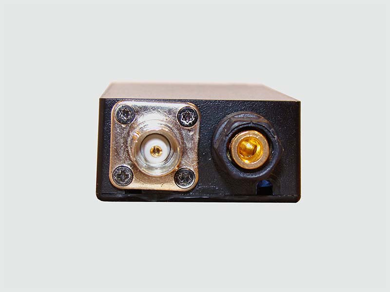
  • Supported new HS512 Max oscilloscope
  • Improved PDF reports

Fixed bugs

  • Hantek 6022BE not recognized
  • User Logout need to reconfigure the file folder to see the waveforms
  • PDF Report has graphic issue when generate while moving the waveform
  • Crash on add photos from Camera to waveform (if Camera permission not enabled)
  • Calibration halt for HS502 in some case
  • 360/720deg graph buttons disappear too soon
  • Report wrongly generated in Automotive module when background is dark
  • Waveform thumbnail wrongly generated in Automotive module when background is white

2.4.4 (438) May, 2024

Improvements

  • Better zoom and scroll function
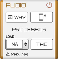
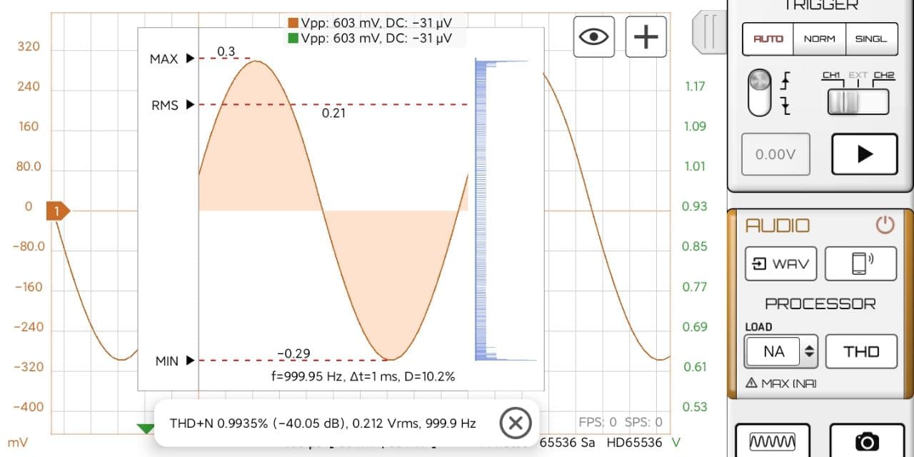
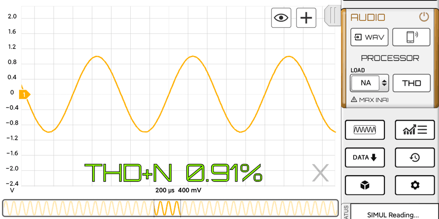
  • Improved THD function (Audio Module)
  • Improved Notes with better text on multiline management
  • Improved waveform save speed
  • WAV files can be imported also in Automotive Module up to 4 channels
  • Improved Flags (can create flags manually and numbers are recomputed after moving or adding flags) (Update 2024)
  • Cursors lock function (Update 2024)
  • Optional buttons in Tools disappear after longer time
  • New keyboard for custom probe settings
  • Waveforms can be sorted (Update 2024)
  • New device: Phone Internal Accelerometer

Fixed bugs

  • Notes position not correct in Oscilloscope mode, after loading
  • Cut waveform in Automotive mode did not move correctly Notes and Flags
  • Wrong XML formatting in some case for the HXML files
  • Crash on reset HS502 calibration data
  • Crash on WAV files import

2.4.3 (429) Apr, 2024

Improvements

  • New device supported: WitMotion WT9011
  • Added velocity stat for Accelerometers (in mm/s)
  • Upgraded RS232 UART decoder (digital module – update 2024)
  • New RS485 MODBUS decoder (digital module – update 2024)
  • New LIN decoder (digital module – update 2024)
  • Better labels for vertical cursors (update 2024)
  • Report supports longer file names
  • Improved CAN decoder
  • Channel 1 can be moved in Automotive Mode
  • Higher resolution design for bigger screens
  • Upgraded digital module management (major upgrade)
  • Added modules and settings button in Automotive Module
  • New Share via Cloud V2.0
  • UART decoded signal can be Exported in .CSV

Fixed bugs

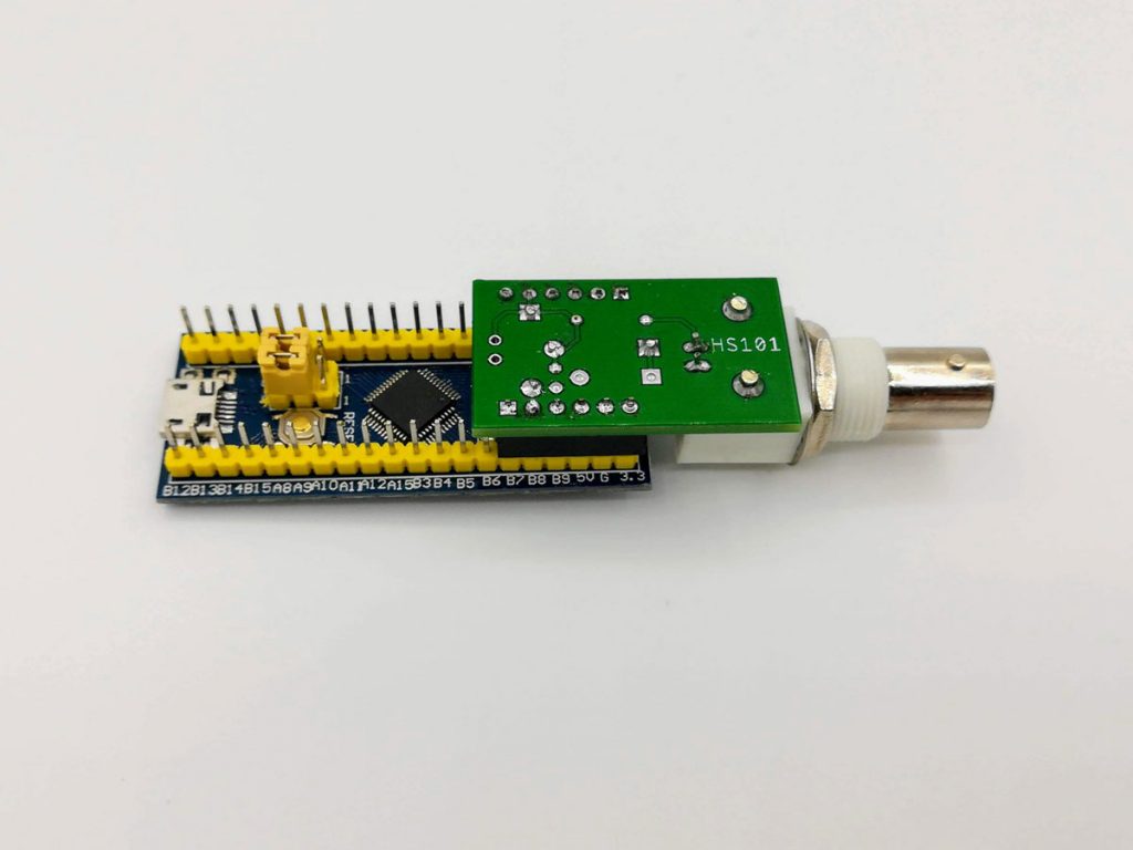
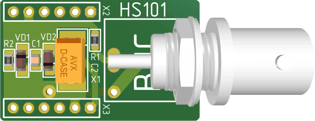
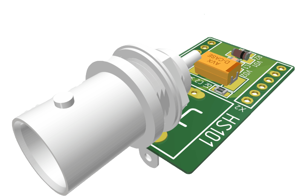
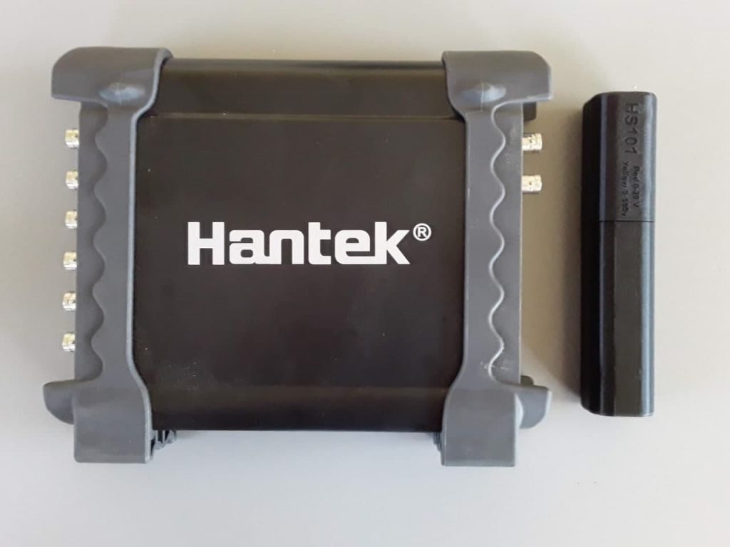
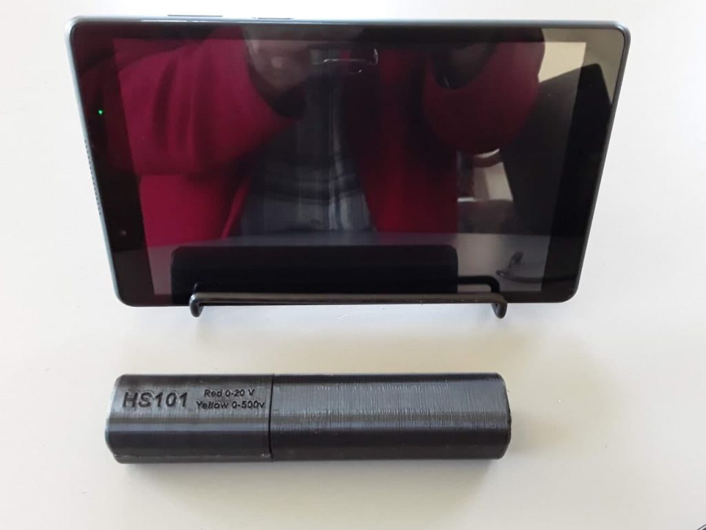
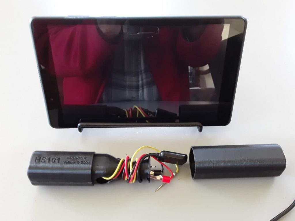
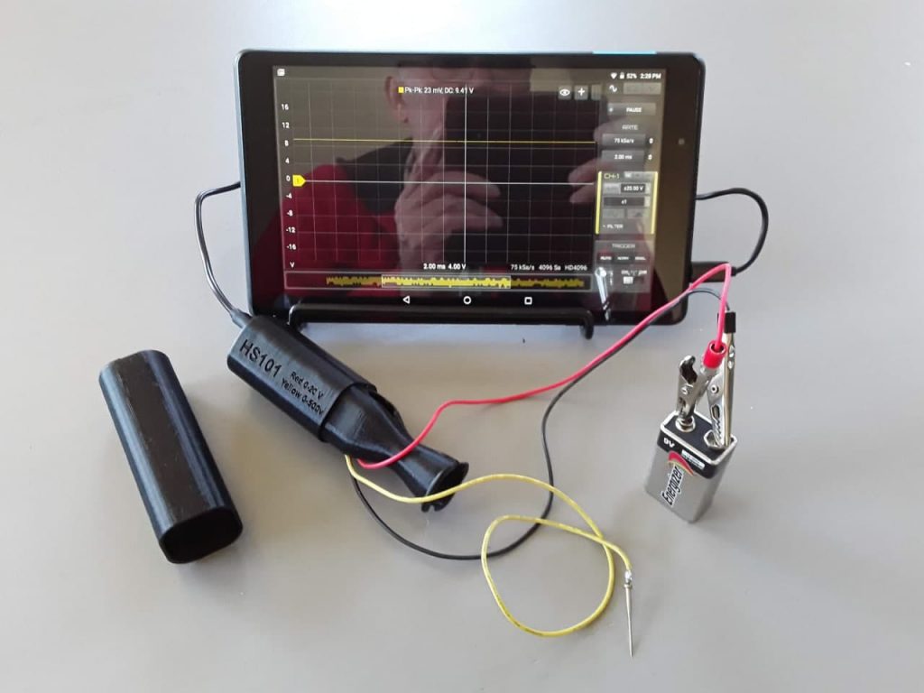
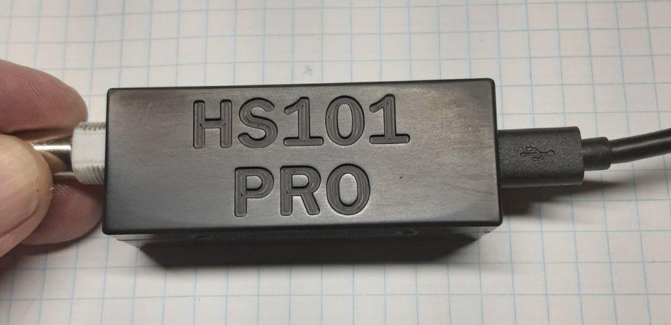
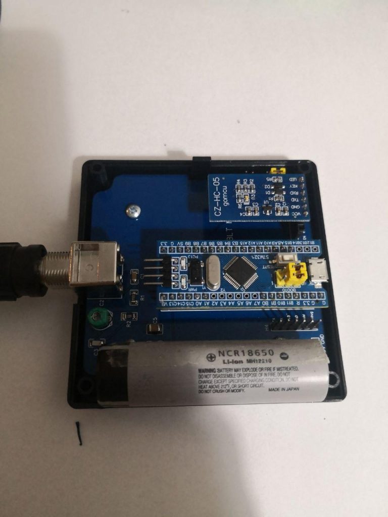
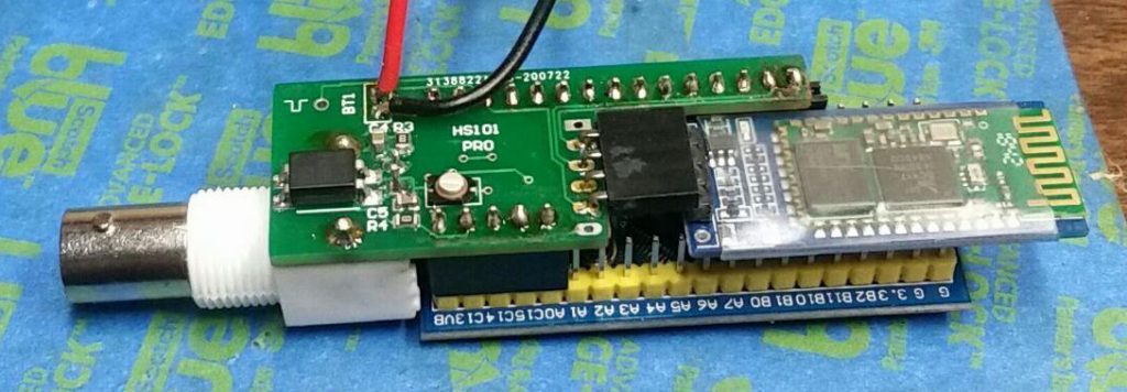
  • HS101 Bluetooth oscilloscope did not work on latest Android versions (> O version)
  • HS-ACCEL DIY version could not connect
  • Issue in scaling Math Channel in Automotive module
  • Fixed driver for Hantek 6074
  • Could not enable bluetooth in Android 14
  • Crash due to Bluetooth in some device
  • Crash in report creation in Automotive mode
  • Bluetooth authorization not recognized for devices without GPS
  • Fire Order Overlay could not move well in some case

2.4.2 (408) Dec, 2023

Implemented enhancements

  • Added inH2O unit for probes
  • Optimized CC-80 Current Probe settings (need to download again the probe configurations)
  • Added Zoom behaviour option among XY or only Y (Update 2023)
  • Removed auto zoom and time set on acquisition start (the screen keep last zoom level and position)
  • Added Amplitude Zoom on mouse wheel scroll
  • Automotive Pages for high rates (Update 2023)
  • Improved Zero Offset function in Automotive Module (at acquisition start)
  • Improved vertical cursors (can enable/disable labels)
  • Improved Automotive view management
  • Can set/load/save Report Title for each waveform (Update 2023)
  • Automotive module don’t hide scroller during recording
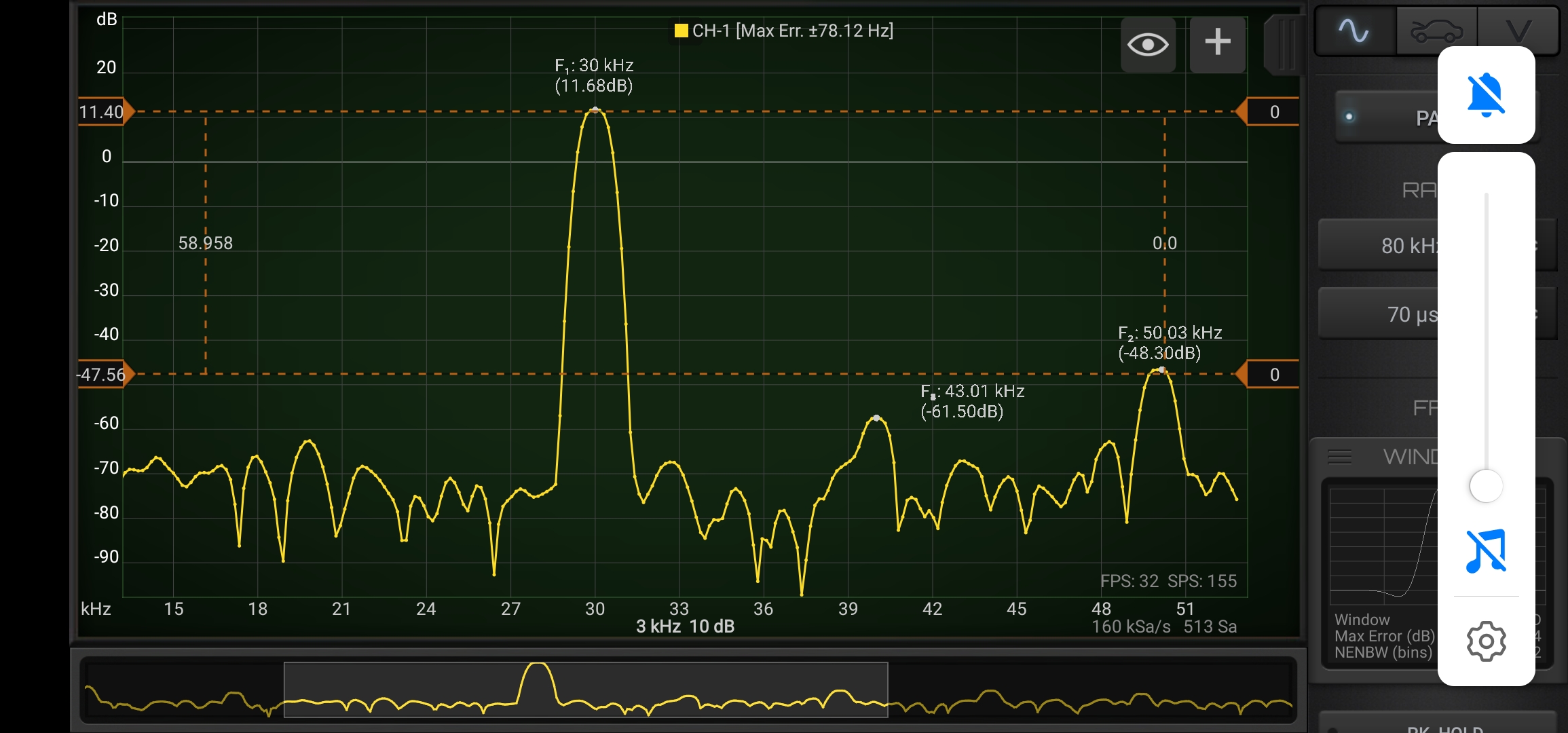
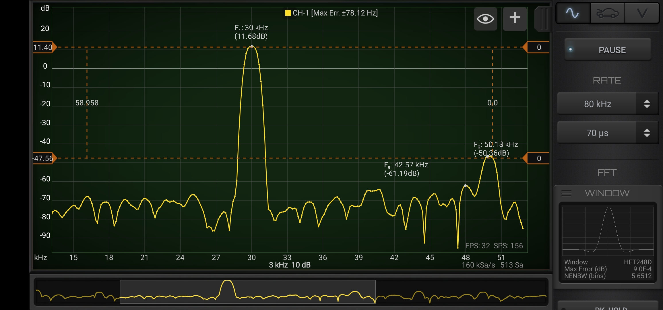
  • FFT data can be exported to CSV (Update 2023)
  • Digital channel can be used in Automotive Module
  • Flag button trigger also Automotive Manual Start
  • Improved messages for Bluetooth Trigger Button

Fixed bugs

  • Wrong voltage values for FOSC53B
  • Automotive waveform disappear in some case (ie. if inverted)
  • Update 2023 button did not appear in some case
  • HS502 multiplier could not be calibrated (now need to use stabilized 5V source)
  • Stats wrong for channel > 1 (Automotive Module)
  • HS-ACCEL (DIY edition) has wrong units (V instead of G)
  • Automotive Zero Level has wrong values
  • Math module bug in Automotive Module
  • Empty visualization on loaded file in Automotive Module
  • Oscilloscope mode could not load files first time without oscilloscope connected or Demo mode
  • Menu UI fixed for Android 13
  • Crash in Android 14
  • Cloud service don’t work
  • HS402 wrong values on start for V/A device
  • App restart when Bluetooth device get connected or disconnected
  • HS502 freeze on voltage change + roll-mode + trigger
  • Automotive mode auto-size waveform function (3) did not work

2.4.2 (389) Sep, 2023

Implemented enhancements

  • Some design detail improved
  • Updated Google and Huawei libraries at latest versions
  • Duty Cycle Math function (update 2023)
  • Support for new Fosc53C WiFi oscilloscope
  • Support for new HS512
  • Added Time/Div control in Automotive Module (update 2023)

Fixed bugs

  • HS502 block in some case
  • Wrong pin for custom AC/DC mod on Hantek 6022BL
  • Automotive Module not enabled for HS502 in case the user has no other licenses
  • Wrong calibration data for latest LOTO OSC-H02

2.4.2 (380 Beta) Mar, 2023

Implemented enhancements

  • HS402 supports new hardware variation (V/A Logger)
  • System Settings show also Data and Cache size and allow to clear the cache (Update 2022/2023)
  • Improved file manager performances (need to clear the cache first time after update)
  • New Histogram stats function (Update 2022/2023)
  • Probes Management keep always x1 probe

Fixed bugs

  • HS402 rate error when enable/disable channel
  • Math Module issues in Oscilloscope Mode
  • Digital module did not show the list of available analog channels
  • HS502 Licensing
  • Crash on Math Channel statistics

2.4.1 (375) Feb, 2023

Implemented enhancements

  • HS502 can run on any android device without app store
  • Better colors for Horizontal Cursors on White Background
  • File Explorer show the presence on the Digital Channels in the waveform
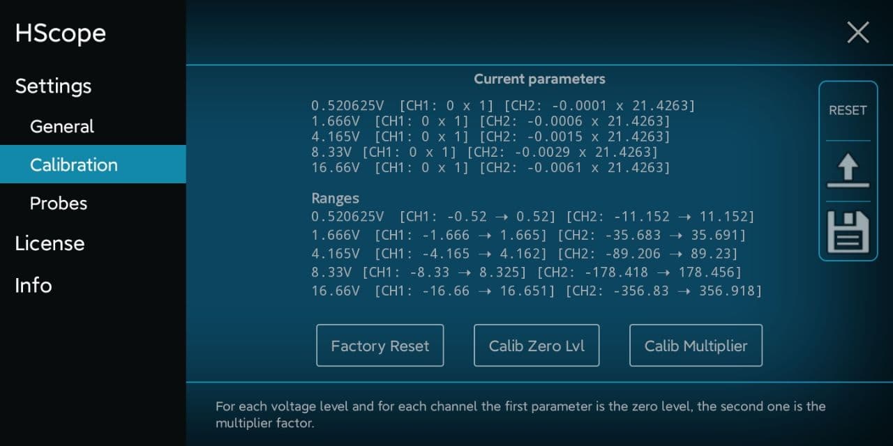
  • Better visualization for Calibration Data
  • Better Fire Order Overlay design (Automotive Module)
  • Filters introduce zero-phase shift
  • Improved WAV exporter
  • Improved Math Demodulation function
  • Can apply filters to the result of Math operation (Update 2022/2023)
  • Improved Logger UI
  • Added support for Fosc53B

Fixed bugs

  • HS402 fast switch of rates caused halt
  • HS502 asked license for some new feature
  • Automotive module could not save waveform in some case
  • Horizontal cursors did not work in some case
  • Automotive module wrongly show Digital Channels in some case
  • HT 1008 fixed data error if started with 4 channels
  • Logger CSV import crash
  • Logger channels not updated according selected probe
  • Signal Invert Filter issue (button don’t reflect the actual status)
  • Filters not working is some condition in Automotive Module
  • WAV exporter crash in some case, data could be corrupted
  • Report didn’t show Math channel info in Automotive Module
  • Solved bugs on Logger
HS10X

Built By The Users

If you want to have your project published just drop an email!

HS101

PCB implementation by Vladimir. Files are available on Github

Built by Denis

HS101 Lipstick – Built by Chris (2020)

HS102

Built by Denis

Built by Pablo (2020)

Built by Gabor (2020)

Build by CrispyDragon (2020 – 3D files here)

HS101 PRO

Built by Denis

Built by Dmitry

Built by Welbert (2020)

HS101 PRO – BLT

HScope

Audio Module Intro

Before You Start

This Module license is in addition to the basic HScope license for the supported oscilloscope model.

What You Can Do

The Audio Output Module allow to:

1. Import WAV Files

WAV Files can be imported, analysed, processed and exported in HScope.

2. Hear on the Phone the Signal from the Oscilloscope

The oscilloscope signal can be sent to the phone speaker through real-time data streaming. While hearing the signal you can still analyse the signal with the other functions. Since the oscilloscope can acquire low voltages this function is useful to check low signals in initial amplifier stages.

Note: this function is not supported by all the oscilloscopes. Check your model under the oscilloscopes list.

3. Compute the Output Power of an Audio Amplifier

The Audio Module can compute the output Power (RMS Power) of a Audio Amplifier by connecting the probe to the speaker connections and by selecting the impedance of the speaker in HScope. The maximum power is indicated in the Audio module panel and depends from the oscilloscope maximum input voltage. For increasing it, set a higher oscilloscope input voltage or use a x10 / x20 / x100 probe. The result is shown in real-time on the graph under the RMS value. For this measure you should input a sine wave in the amplifier. This signal could be produced by a portable MP3 player or by another phone App.

Pay attention: the sound generator cannot be the same phone running HScope since it cannot share the same GND of the oscilloscope.

Pay attention: the output of an audio amplifier could have high voltages. The GND of the probe should be connected to the GND of the amplifier or to the speaker wire connected to the GND. If both speaker wires are floating (neither one on GND), then the oscilloscope GND and phone box could be at a dangerous voltage. In this case you may look to some insulation solution like to use capacitors in series both to the probe tip and to the probe GND. (see EEVBLOG)

4. Compute the THD of the Signal

For pure sinusoidal signals you can compute the Total Harmonic Distortion.

5. Input data from Microphone

You can acquire data from microphone input. Available only on phones with at least Android 6.0.

Resources

HS402

HS402-WiFi Building Instructions

If you want to go fast I suggest you to check some guide made by other users:

  • Full Article for the first video: link
  • Project material can be found here in Github, other resources at the end of this page
  • It is suggested to join the Telegram group to get more info and support

Hardware

To build the HS402-WiFi oscilloscope you can choose among these 2 options.

1. Easy Built

You need:

  • HS402 oscilloscope (built with PCB V2.0 or PCB V3.0) with Firmware ver. ≥ 1.7
  • ESP32 Development board (one with ESP32-WROOM first version or ESP32-WROOM-32D), connected to STM32 as following and flashed with latest ESP32 Firmware. Flashing instructions here.
  • You can also use a PCB adapter created by Mikael to connect the ESP32 and STM32 together. Look at this project here, usage video here.

2. Full Built (with PCB v3)

  • A compact built using PCB v3 which integrate all the components, including the ESP32-WROOM chip
  • PCB v3 is composed by 2 parts that need to be separated. Then main PCB is for the standard HS402 USB oscilloscope, the small PCB is the WiFi Module.

You need:

  • Get PCB v3, split the 2 board along the separation line by using a knife on both side and the apply a pression on both side to take the 2 board apart.
  • Solder all the components. A demo of the STM installation for PCB v3 is here.
  • Flash the STM32 and the ESP32
  • Put the WiFi Module over the HS402 long connector (top right)
  • Power from BAT connector (3.6 – 5V) or from USB connector of the STM32

After just follow the User Guide to connect the WiFi configuration page.

Firmware / Software


Powering with Battery

1. With 5V Battery Pack

  • Possible with whatever hardware built

Just connect a classic phone charger to the USB port of ESP32 or of the STM32 to power up the oscilloscope.
You can also disassemble a phone charger and add a switch for power, as done in this video.

2. With 3.7V Lithium Battery

  • Possible only by using the hardware Option 3 in the PCB v3

With the hardware Option 3 in the PCB v3 it is possible to power the oscilloscope directly with a 3.7V Lithium battery. You can add also a micro-charger circuit as in the following schematic. This configuration allow the lower power consumption for this device (around 180mA avg).

Resources

  • Open Source Hardware Schematic for HS402-WiFi V3.0 available here.
HS402

HS402-WiFi User Manual

First configuration

At the first boot the HS402-WIFI oscilloscope creates an Wifi access point with SSID like HS402-F62684. Connect to it with the phone or PC (password: 123456789) and open the browser (everything except Internet Explorer) at address 192.168.4.1, to access the oscilloscope configurations.

In windows you can find it also under Network. Double click on the icon to open the configuration page.

In case you cannot see the oscilloscope in the Network list, in the wifi list just open the preferences of the HS402 wifi and set it as Private since Windows block the device discovery on public networks.

Oscilloscope Configurations

Network

The oscilloscope can work in one of these modes:

Access Point (or AP): the oscilloscope become an access point and the phone can connect to it directly by using its SSID name (for example HS402-F62684). You can configure SSID name, password, IP and WiFi channel. 40Mhz WiFi channel is faster and generally suggested. For the WiFi channel selection it is suggested to run a WiFi scanner to check which channel is more free in your area.

Station (or STA): the oscilloscope connect to an existing access point (for example a residential one) and can be found by HScope in the same network.

You can set 2 different SSID, the oscilloscope will try to connect to the first one, in case of failure it will try the second one, in case not possible the oscilloscope will turn to be Access Point using the access point settings.

Remember to reboot the ESP32 (or press the reset button) to apply the new WiFi settings.

LED Messages

The RGB led connected to the ESP32 development board provides the status of the oscilloscope.

AP Mode: the ESP32 is itself an access point, you can connect to it directly by searching on the available Wi-Fi. SSID like HS402-F62684.
STA Mode (Station Mode): the ESP32 connect to an existing access point / router. The phone / tablet should be connected to the same network to connect to the oscilloscope. You can configure this mode in the ESP32 Webpage.

HScope Configuration

In HScope you need to enable the WiFi connection. This setting in available in the Oscilloscope section:

Configuration Reset

In case you forgot the password of the Wifi in AP mode and cannot access the configuration anymore, just press the BOOT button to reset the configuration to the standard values.

  1. Press and keep pressed the BOOT button for at least 3 seconds. The LED will blink in yellow color.
  2. Release the button, then the LED will blink in red color to indicate the configuration update and the ESP32 will restart automatically in AP mode with the default SSID name and password.

Possible Issues

The app disconnect from the oscilloscope after a while

This may be due to the Android phone/tablet that disable automatically from the ESP32 network and connect to another network. To avoid this you need to disable in the Android settings the automatic connection to stronger networks.

Remove WiFi automatic connection to strong network in Android. In this way the oscilloscope won’t disconnect if the Android tablet detect a stronger WiFi connection.

The app disconnect and reconnect

This case has been found from some user and it is related to the fact that the phone/tablet run other processes using the networking and slowing down the connection with the oscilloscope which goes in timeout and then reconnect. This has been solved by deactivating the Bluetooth in the Android tablet/phone (enabled Bluetooth used to run frequent scans blocking the WiFi communication).

HS402

HS402-WiFi Built By The Users

If you want to have your project published just drop an email!

Built by Mikael (2021)
HScope

Automotive Waveforms

Here some sample of automotive waveform captured by users.

HScope

Automotive Module

This module is not supported by all the oscilloscopes and it is not supported in the same way. Check more under each oscilloscope page.

The Automotive Module allows lengthy and continuous real-time acquisition at lower sampling rates. Although this acquisition method is usually used for car diagnostics, it can be used in several other applications. Max sampling rate varies by oscilloscope.

Before You Start

The Automotive Module license is in addition to the basic HScope license for the supported oscilloscope model.

The minimum requirement for this module is a device with 4GB RAM or more.

1. Start Recording

Rate and channel parameters to be configured prior to a recording start.

Maximum recording time is sample rate dependent and displayed under the recording button.

Recording automatically starts when a significant change in the input signal is detected.

After the recording start the parameters cannot be changed unless you run a new recording.

2. Analyze The Data

Recorded data can be zoomed and scrolled with fingers. Cursors appears as you click with 1 or 2 fingers on the horizontal axis.

Labels Tool

This tool is useful to perform the relative compression test. You can set any number of cylinder and their firing order. Example below:

720° Tool

This tool allow to add the overlay of 720 degrees of crankshaft rotation in pressure waveforms. Pink cursor is moveable (on bottom part). By clicking on the gray labels is possible to show or hide the text.

Annotations

Coming soon

Cylinder Timing Overlay

This overlay allow to visualize the cylinder status at a certain time. More info in the following demo.

3. Import / Export

This module allow export and import of waveform in an efficient open format. Waveforms are saved in .zip format in the following phone folder: /Download/HScope/Automotive
Users can share the saved waveforms just by copying from and to this folder. Filenames can be changed with Android file explorer. Waveform preview is available to remember the waveform before importing.

Import / Export Tool

Other

Hardware Limitations

This functionality is not commonly found in commercial oscilloscopes which are mostly ‘memory based’ and not ‘data streaming based’. Continuous Data Acquisition capability and speed depends strongly on hardware architecture of each oscilloscope model and the ability to ‘overclock’ its drivers.

For example the Hantek 1008 allows a maximum rate of 2KSa/s with this module, sufficient for crank position sensor diagnostics. HS10X DIY Oscilloscope Series allow up to 100KSa/s. FX2 Chipset based oscilloscopes allow a maximum continuous sampling rate up to 125KSa/s.

Resources

HS402

HS402 – Additional Modules

Hardware Buttons Module

By connecting the PCF8574 I2C module it is possible to have 8 hardware buttons to control the oscilloscope. These are the pin that should be connected to the STM32: GND, VCC (5V), SDA, SCL, INT. Buttons are triggered by connecting the P0-P7 pins to GND. The configuration jumpers on the PCF module should be as in the picture (it use the base address).

Button functions

  • P0: Start / Stop
  • P1: Rate up
  • P2: Rate down
  • P3: Fit waveform to screen
  • P4-P7: (not assigned)

PWM Module

HS402 can generate PWM output. A MOS driver like the MOSFET IRF520 Module Board can be used to control loads. Here the schematic of connections. A video about how to use the HScope PWM module is shown under. The IRF520 has been tested at 1KHz PWM frequency and showed low pass characteristics so it is not suggested to use an higher frequency.

Additional Resources

HS402

HS402 – Building Instructions

What do you need

  • STM32F411 Development Board (Black Pill)
  • USB-TTL adapter to flash the STM32 (or ST-LINK in alternative)
  • HS402 PCB with all its components (or custom circuit for the analog part)
  • USB OTG cable for the phone (examples provided following)

Quick Video Instructions

Article link.

Schematics & Built

Notes

  • Other STM32F411 development boards can be used, the important is that the main crystal is 25MHz
  • On the schematic are indicated 2 or 3 hardware options. One exclude the other.


Flash the Firmware

The firmware flashing is made with the app STM32 Utils with an OTG adapter connected to the phone and an USB-TLL adapter connected to the OTG adapter. After connecting the phone to the STM32 Black Pill board like in picture, the red led light up.

By pressing the buttons on the Black Pill as in picture, the board enter into the STM boot loader and it is ready to be flashed. On the App:
1) Go to Init Chipset and check that the app read the chipset


2) Go to the Blue Box icon and in the list under vendor Martinloren select HS402 Oscilloscope, select the chipset from the variants (STM32F411 or STM32F401), then FLASH FW.

3) After flashing disconnect the USB-TTL cable from the STM32 board and connect the STM32 to the phone through the OTG cable. Open HScope, the app should show you the signal from Channel 1.

Connection

First Setup / Calibration

When the oscilloscope is connected go in HScope Settings, General - Hardware. Here:

  • Set the Model to HS402 and Input Type to PRO. When you do this change also the option Hardware AC/DC Coupling will be enabled automatically.
  • Disconnect and reconnect the oscilloscope to get the new configurations.

You can also Enable the input buttons if you have installed the corresponding I2C module.

Offset Calibration

  • (required just for Hardware Option 1) Connect Channel 1 probe to its GND.
  • (required just for Hardware Option 1) Rotate the precision variable resistor (R9) until the software show a DC voltage quite near to 0. This trimmer requires a lot of turns. Make sure with a multimeter that its value is around 1Kohm before proceed with the fine tuning.
  • For each channel do the Calib Zero Lvl procedure in the Settings -> Calibration.

Frequency Calibration

  • Enable the PWM signal using the PWM module (red square icon in the right menu, then open the module). HS402 will generate a square wave on pin B15 (1kHz initially).
  • Connect the probe to pin B15. Use an high rate, i.e. 450KSa/s and turn the variable capacitor until the rising part of the square wave reproduce a good square. Do this for each channel.

Now the device is calibrated in frequency response.

Multiplier Calibration

For this calibration you need an accurate voltage source, for example 3.3V or 5V from a voltage stabilizer. 5V from USB port is not accurate and should never be used for this calibration. Batteries also should not be used. At least you can use LM7805 or this kind of linear voltage regulators.

  • For each channel do the Calib Multiplier procedure in the Settings -> Calibration.

HW Debugging

Here the tests you can perform in case of issues:

  • Check that PGND is approximately around 1.65V respect GND. In Option 1 the R9 trimmer requires a lot of turns to get the offset near the 0. With a multimeter you can test it reach around 1Kohm and then fine tune the zero level with HScope. A3 and A5 pins (analog inputs) also should be at the same voltage with no input signal is applied.
  • With a multimeter check that there are no shortcuts among the pins B3, B4, B5, B6 (these are connected to the PGA (U1, U3) which are very small and are easy to get shortcuts between the pins).
  • Check that voltage change on C4 and C5 when on HScope you enable/disable AC/DC option on the channels. To check that the AC/DC coupling works just apply a battery to the input. When DC is selected you should read the voltage of the battery, when AC is selected you should read 0V.

Hardware options

Hardware options in the schematics are meant to give the possibility to the user to have a lower noise by using more components. Higher option number means a better circuit.

Schematic Option 2 and 3

This option provide a stable reference voltage to the STM32 ADC, by installing the part indicated in the Schematic as Option 2 and 3. It requires also a modification on the STM32 board in order to bring the Vref pin from the STM32 to one of the pins of the development board (PA2). One component should be removed (the inductor) and a jumper should be created to PA2 according the picture under. PA2 is inactive and used just to provide the Vref signal. Demo video here.

Option 2 just show a greater cross-channel noise respect Option 1: 0.25% vs 0.05%.

Note: after this modification the STM32 board will work only if 3.3V is applied to PA2 (now Vref)!

Arbitrary Input Range

You can design the input ranges for each channel according your needs. For example it is possible to have the maximum voltage to ±5V or to ±50V. Channel input ranges can be also different (for example a channel has max voltage ±16V and the other channel ±5V).

  1. Calculate R2/R3 (or R6/R7) resistors values according the required range. Pay attention the sum of these 2 resistor should be around 1Mohm.
    a) R2 + R3 = 1Mohm
    b) ±Range = 1.65 * (R2 + R3) / R3

    Example: Range = 1.65 * (910k + 100k) / 100k = ±16.66V
  2. Do the multiplier calibration of the channel. After the software will show the voltage ranges according the hardware.

Warning: do not exceed 50V input range since the input is not isulated from GND and from the phone, leading to a possible electrocution.

Additional Resources

HS402

HS402 – Tests (USB Connection)

The following tests are referred to PCB V3.0 without any box. Hardware option 3 (lowest noise).

Base Noise Analysis

Tests performed without probe, open BNC connectors.

Noise at highest voltage range

This test shows the following base noise:

  • @2MSa/s 0.15%
  • @400kSa/s 0.1%
  • @200kSa/s 0.05%
  • @50kSa/s 0.02%

Noise at lowest voltage range

This test shows the following base noise:

  • @2MSa/s 0.7%
  • @100kSa/s 0.4%
  • @50kSa/s 0.2%
  • @25kSa/s 0.08%

Cross channel noise

Cross channel noise is present. Part of the signal of one channel can be found on the other channel as noise.

When one of the channel saturates (input voltage greater than the maximum range) then the cross channel noise is greater. Channel saturation should be avoided during use.

In the following examples cross channel noise can generate a noise up to 0.5%. At the same conditions without cross noise the base noise would be 0.15%.

Sample Waveforms

Sample signal acquisition from a signal generator after calibration.

Tests with FFT

ADC 8-bit vs 9-up bits

Comparison between 8-bit ADC (provided by selecting the highest rate) and the next rate.

Guide

Audio Module

Note: this Module requires a specific license in addition to the basic HScope license.

What You Can Do

The Audio Output Module allow you to:

1. Import WAV Files

WAV Files can be imported, analysed, processed and exported in HScope.

2. Hear the input signal from Channel-1 on phone

The oscilloscope signal can be sent to the phone speaker through real-time data streaming. While hearing the signal you can still navigate in the Oscilloscope graph or switch to the FFT graph. It works at sampling rates 25KSa/s and 50KSa/s. Since the oscilloscope can acquire low voltages this function is useful to check low signals in initial amplifier stages.

Note: this function is not supported by all the os

3. Compute the Output Power of an Audio Amplifier

The Audio Module can compute the output Power (RMS Power) of a Audio Amplifier by connecting the probe to the speaker connections and by selecting the impedance of the speaker in HScope. The maximum power is indicated in the Audio module panel and depends from the oscilloscope maximum input voltage. For increasing it, set a higher oscilloscope input voltage or use a x10 / x20 / x100 probe. The result is shown in real-time on the graph under the RMS value. For this measure you should input a sine wave in the amplifier. This signal could be produced by a portable MP3 player or by another phone App.

Pay attention: the sound generator cannot be the same phone running HScope since it cannot share the same GND of the oscilloscope.

Pay attention: the output of an audio amplifier could have high voltages. The GND of the probe should be connected to the GND of the amplifier or to the speaker wire connected to the GND. If both speaker wires are floating (neither one on GND), then the oscilloscope GND and phone box could be at a dangerous voltage. In this case you may look to some insulation solution like to use capacitors in series both to the probe tip and to the probe GND. (see EEVBLOG)

4. Compute the Audio Distortion (THD+N)

The primary job of any audio device is to faithfully reproduce or transmit the audio signal that is input to it. An ideal, linear audio device will produce an output signal that is an identical scaled version of its input signal. Anything that alters the input signal in any way, other than changing its magnitude, is known as distortion.

A classic means of detecting audio signal distortion is to stimulate a device under test (DUT) with a pure sine wave and then conduct a spectral analysis of the DUT output. Sine waves are used because a pure sine signal has the unique property that all its energy is concentrated at a single point in the frequency spectrum. This makes it easy to analyze the output from the DUT for unwanted distortion components. When a single sine wave is used as the stimulus, nonlinearities in the DUT cause harmonic distortion, wherein distortion components occur at harmonics (integer multiples of the sine signal’s frequency, or fundamental frequency).

Total Harmonic Distortion Plus Noise (THD+N)

The THD+N technique is the most common method of measuring harmonic distortion. In its basic form, it is implemented with a sharp notch filter tuned to the fundamental sine frequency, a bandwidth limiting filter, and an rms level meter. The notch filter removes the fundamental sine signal, leaving a residual signal which consists of the harmonics and noise. The THD+N Ratio is calculated as the bandwidth limited rms level of the residual divided by the rms level of the entire signal.

Samples for testing

If you want to test the THD processor you can import WAV files with known distortion. For example the file you can find at this link.

Resources

Martinloren