You can use the headphones (wired or bluetooth) to control some function of the app, for example during automotive recording you can press a button on the headphones and have a flag on the graph at the time of button press to remember the time when an event occured.
You can use commercial headphones (with buttons) or you can make a custom cable with up to 4 buttons.
Button functions are configurable in HScope.
Configuring button functions in HScope
In HScope Settings (General Settings) you can associate buttons from Keyboard or Headphones buttons to HScope functions.
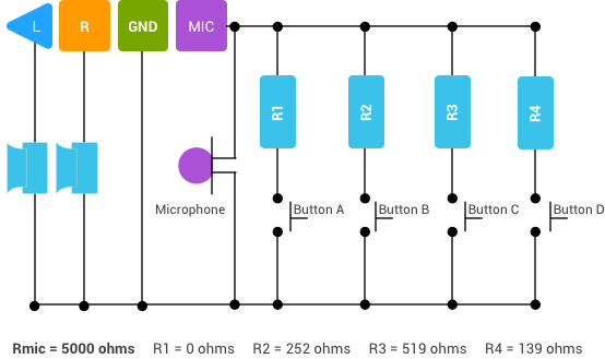
Build a custom cable
You can have a simple headphone cable with a single button or can have a console wih up to 4 buttons. Here is the schematic to implement up to 4 buttons with an headphone cable (speakers and microphone are not required). More informations here.
You can use bluetooth keyboard and mouse to control the app for example on televisions or screens with Android TV Boxes. Here is the list of keys you can use to control some of the functions:
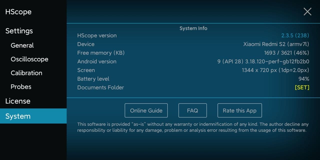
In the System Settings you can see your device information.
System Panel
Set the Documents Folder (Android 10+)
You need to set the Documents Folder in order to save the app configurations and waveform data safely in a public folder of your phone.
Case 1: First HScope Installation
You can create and select this folder in your Documents or Download folder (ie. HScope under /Documents/). After creating the app data folder just select it and confirm.
Case 2: HScope app upgrade
Select the existing HScope folder under /Downloads/ or /Documents/. Follow the procedure in this Guide under Introduction → Android 10+.
Change log
Click on the HScope version number to open the information about the latest app release.
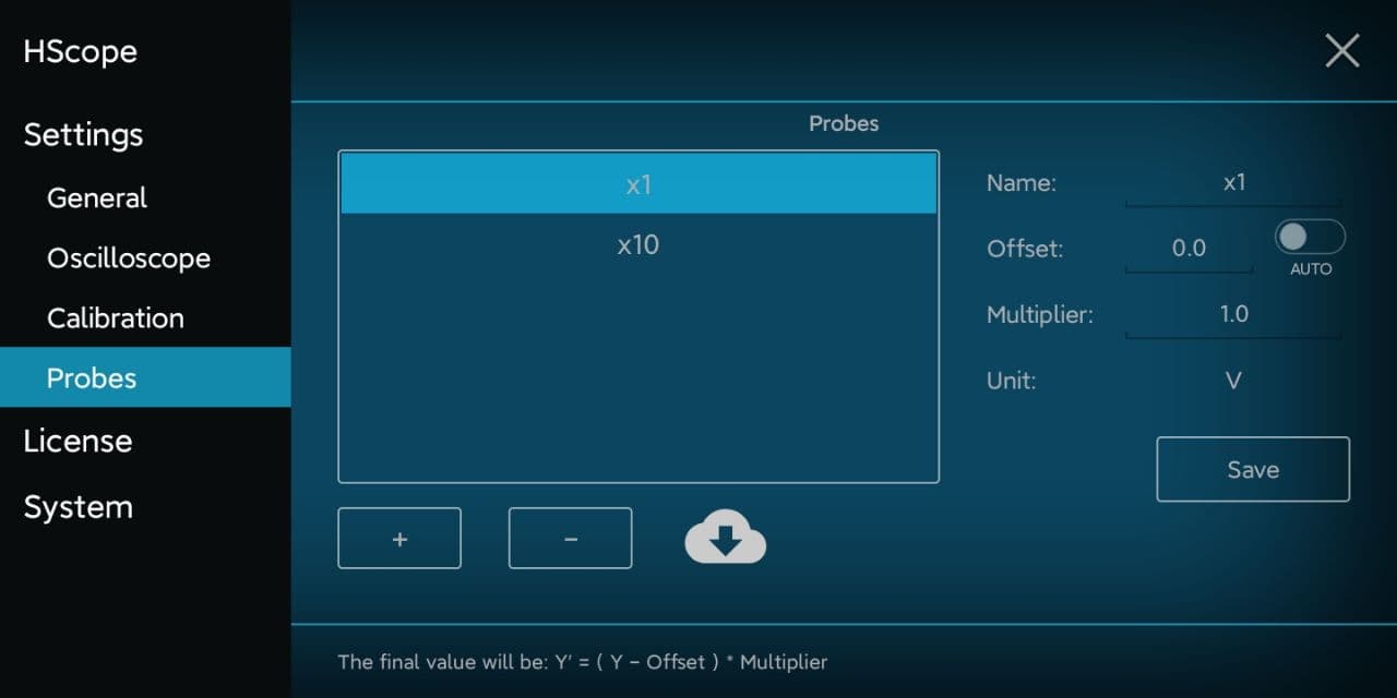
You can add, remove, configure or import probes in the Settings → Probes panel.
Probe Settings Panel
Select a probe from the list to see and change the probe settings (on the right).
Click on “+” button to add manually a new probe.
Click on “–” button to delete a selected probe.
To calculate the values for a new probe you can try this online tool.
Backup Your Probes
You can find a backup of your probes configuration in the Documents Folder selected in Settings → System. The backup file is called Probes.cfg (ie. /Download/HScope/Probes.cfg). HScope will automatically save the probes configuration on this file.
Warning: in case you don’t have selected a Documents Folder in Settings → System then this automatic backup won’t work.
Import / Download Probes
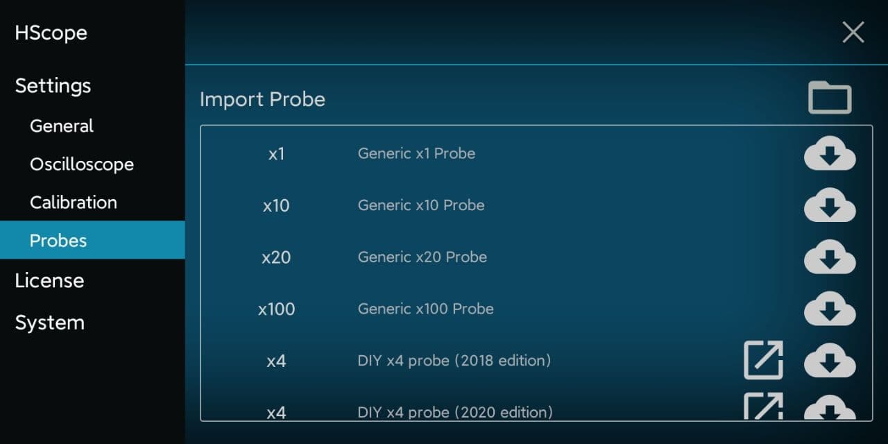
Click on the Cloud icon to access the Import Probe screen. Here you can import probes configurations from a probe backup file or from the cloud.
Import Probe Screen
Import from File
Click on the folder icon on top/right of the screen to load a saved Probes.cfg file. You can also have renamed this file (ie. Probes_2021.cfg). The important for this file is that it end with .cfg extension.
Only new probes will be imported, if a probe already exists with the same name it won’t be imported.
Download from Cloud
On the list you can download single probe configurations from common brands or DIY probes.
Click on the cloud download icon to get the probe configuration.
DIY probes are available in the cloud list with link to instruction how to build it. In case of DIY probes you can click on the arrow icon and open the page for the probe building.
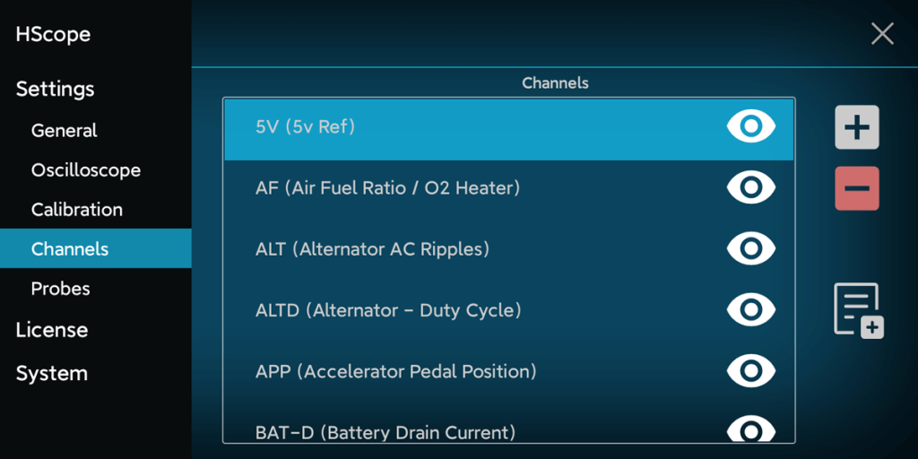
In Settings → Channels you can see the available names that can be assigned to the oscilloscope channels. Set a specific name for a channel is just a self reminder for the visualized data. No function is associated with the Channel naming.
If you don’t use some channel name of them you clicking on the eye and hide it.
You can add or remove custom names with the + and – buttons. You can remove only custom names previously created.
When you modify this list HScope saves the current configuration in a file called Channel_Names.cfg under your HScope document folder.
By clicking on the document icon with the + on you can import a custom names list from file (from example a configuration saved on another phone).
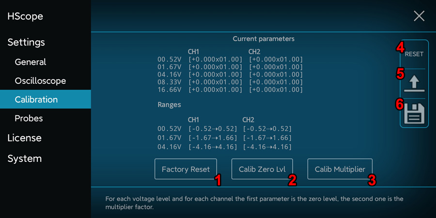
Calibration parameter are showed and can be adjusted just when the oscilloscope is connected on the phone.
1. Factory Reset
Set the calibration parameters according the calibration data stored in the oscilloscope (it works just for few models, check this possibility in the oscilloscope specific webpage).
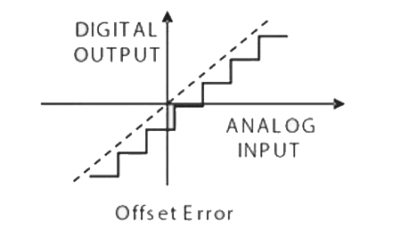
2. Calibrate Zero Level (or Offset)
Allow to set the output to 0V when the probe is connected to its ground. It practically reduce the offset error.
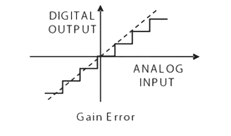
3. Calibrate Multiplier (or Gain)
Allow to reduce the gain error of the oscilloscope, by using an accurate reference voltage. You can also repeat this procedure with different reference voltages. In this case, for each channel, start from lower reference voltages to higher ones.
First it is necessary to calibrate the Zero Level, then the Multiplier Factor
4. Reset
Reset the calibration data.
5. Load
Load the calibration data from a file.
6. Save
Save the calibration data to a file.
For each channel is possible to calibrate the Zero Level (b) (so that when the probe is connected to the GND the result of the measure is 0 Volts) and the Multiplier factor (m). Assuming the ADC measured values are on a straight line the Multiplier factor allow to adjust the inclination of the ADC line according the equation y=(x+b)m. First it is necessary to calibrate the Zero Level, then the Multiplier Factor.
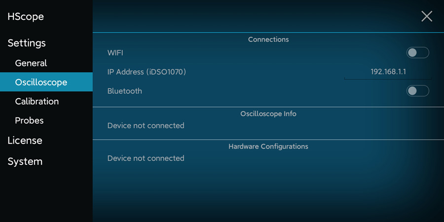
Here you have the settings related the oscilloscope and you can see the oscilloscope information (when connected).
Connections
Enable the WiFi or Bluetooth connection in case you have these kind of oscilloscope. If not disable them so the app would not search on these networks.
The IP Address (WiFi) configuration is currently used only for iDSO1070 oscilloscope in case the user assign a custom IP address to this device in the WiFi network.
Oscilloscope Info
Here you can see the hardware information when the oscilloscope is connected. This screen is refreshed in real-time.
Hardware Configurations
Here you can set additional oscilloscope hardware configurations, according the oscilloscope capabilities.
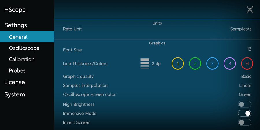
In the General Settings you can see your device information.
Units
You can change the rate unit in the menu to show Samples/s or Bw (Bandwidth). The 2 units are equivalent.
Font Size, Line Thickness/Color
They change the graph and data aspect.
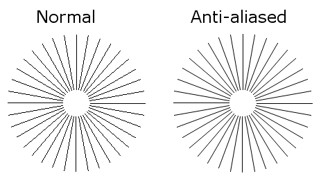
Graphic Quality
You can enable Antialiasing for the lines of the signal. Anti-aliasing is a method by which you can eliminate jaggies that appear in graph lines.
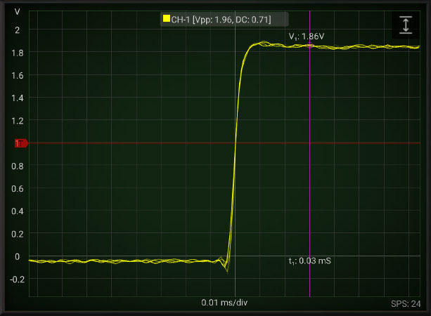
You can also enable the Phosphor effect which keep drawn the old signal patter on the screen for a certain time, like in the old oscilloscopes. With this effect you may see better the signal fast variations (eg. noise).
Decay Phosphor effect
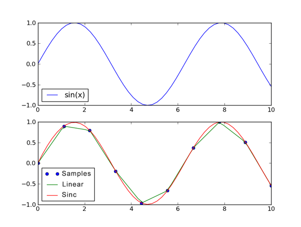
Samples Interpolation
When the Scope acquire a signal we receive just samples but we don’t know what’s the signal shape between the samples. We can just connect the dots (Linear Interpolation) or better we can reconstruct the original signal according the Whittaker–Shannon formula (Sinc Interpolation).
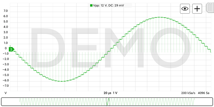
Step Interpolation is generally used for digital signal, it shows one horizontal line for each sample.
High Brightness
Keep the screen at full brightness when using the app.
Immersive Mode
Allow the app to run in full-screen mode.
Invert Screen
Invert the screen visualizzation to be more convenient according the position of the USB cable on the Android device.
Alert Sound
Set the type of sound used for alerts (used in alarmed cursors to advice that the signal passed a certain threshold).
FPS/SPS
Enabling this option it is possible to know how many acquisitions are currently taken by the Scope (SPS: Scans Per Second) and how many time the screen is refreshed (FPS: Frame Per Second). This number may vary from device and rate settings.
Send anonymous usage statistics
It send to HScope website information about your phone model when successfully connect to an oscilloscope. In this way it is possible for all other users to know what phone model has been successfully tested to work with USB oscilloscopes. List of working phone models is available here.
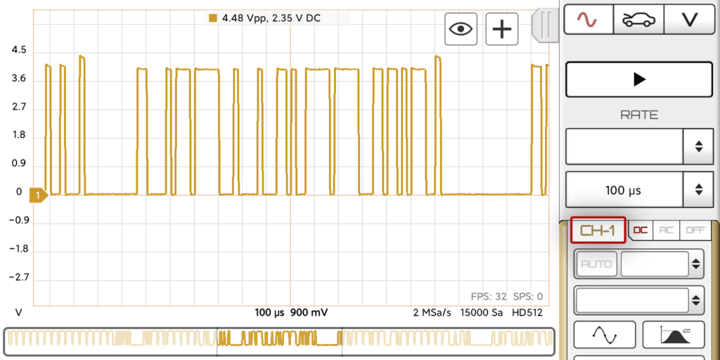
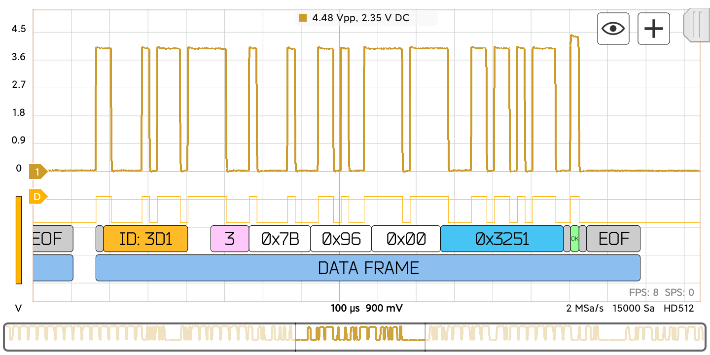
CAN (Controller Area Network) Bus is a serial protocol used in automotive and industrial machinery to allow microcontrollers to communicate with each other. It uses differential signalling (with signals named CAN H and CAN L) to increase noise immunity.
The oscilloscope sampling rate must be at least 3 times higher than the CAN speed. In case the CAN speed is 1Mb/s, you need to set the rate at least 3-4MSa/s.
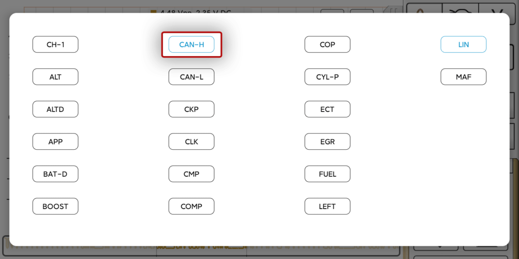
Activating CAN Decoder
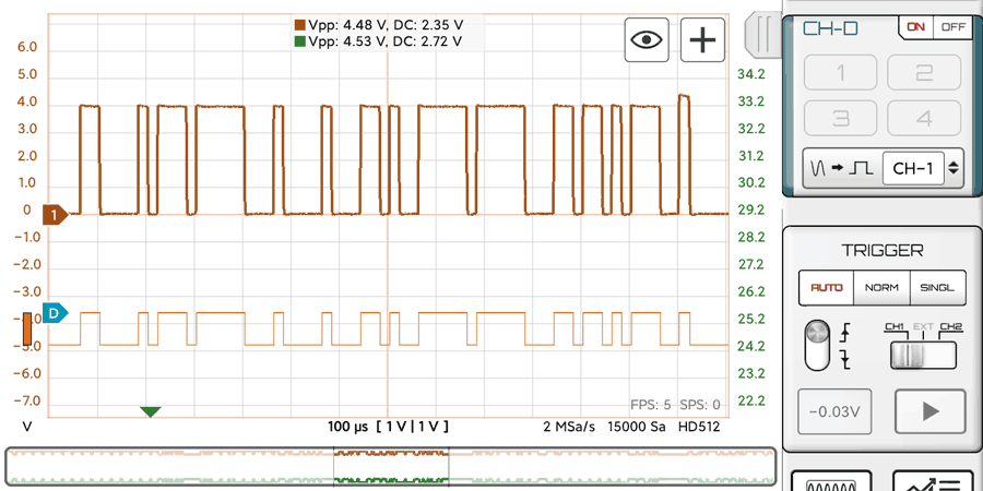
1. Assign the name to the channel that acquired CAN-L signal. This will create e digital signal in the Digital Module from the analog data.
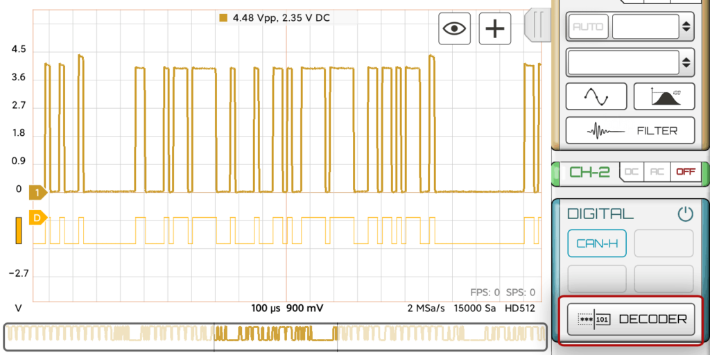
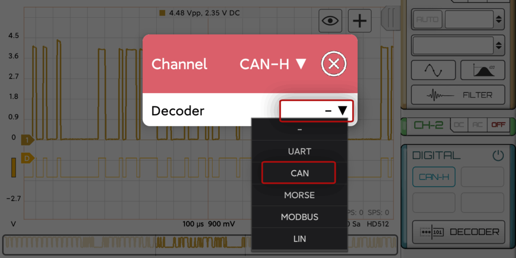
2. Select the CAN decoder for the digital signal.
Now you should see the decoded data.
Fields: (all numbers in Hexadecimal format)
Field name
Length (bits)
Purpose
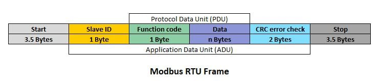
Start-of-frame (gray)
1
Denotes the start of frame transmission
Identifier (yellow)
11
A (unique) identifier which also represents the message priority
Data length code (DLC) (pink)
4
Number of bytes of data (0–8 bytes)
Data field (white)
0–64 (0-8 bytes)
Data to be transmitted (length in bytes dictated by DLC field)
CRC (blue)
15
Cyclic redundancy check
CRC delimiter (gray)
1
Must be recessive (1)
ACK slot (green or red)
1
Transmitter sends recessive (1) and any receiver can assert a dominant (0)
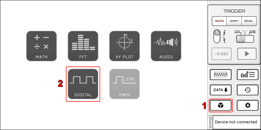
Digital Module requires its license in addition to the basic oscilloscope license.
Select Digital Module from the modules menu.
You can see a new panel for the digital channels*. In case your oscilloscope has digital inputs you will be able to turn ON/OFF the digital channels and see them on the screen with the analog channels.
* You can see this panel also if the oscilloscope has digital inputs but without the Digital License you cannot access the additional features of this module.
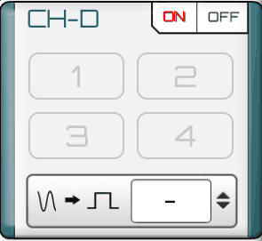
Analog to Digital converter
Even if your oscilloscope doesn’t have digital inputs, you can convert one of the analog channels to a digital signal with the last control on the panel.
The converted signal will be the Logic Channel 5 (or L5).
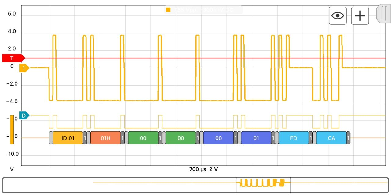
Protocol Decoding
Click on the blue channel cursors on the left. On the top on the screen you will see a Settings icon. There you can select the digital channel and apply a protocol decoder.
We use technologies like cookies to store and/or access device information. We do this to improve browsing experience and to show personalized ads. Consenting to these technologies will allow us to process data such as browsing behavior or unique IDs on this site. Not consenting or withdrawing consent, may adversely affect certain features and functions.
Functional
Always active
The technical storage or access is strictly necessary for the legitimate purpose of enabling the use of a specific service explicitly requested by the subscriber or user, or for the sole purpose of carrying out the transmission of a communication over an electronic communications network.
Preferences
The technical storage or access is necessary for the legitimate purpose of storing preferences that are not requested by the subscriber or user.
Statistics
The technical storage or access that is used exclusively for statistical purposes.The technical storage or access that is used exclusively for anonymous statistical purposes. Without a subpoena, voluntary compliance on the part of your Internet Service Provider, or additional records from a third party, information stored or retrieved for this purpose alone cannot usually be used to identify you.
Marketing
The technical storage or access is required to create user profiles to send advertising, or to track the user on a website or across several websites for similar marketing purposes.