CAN Decoder
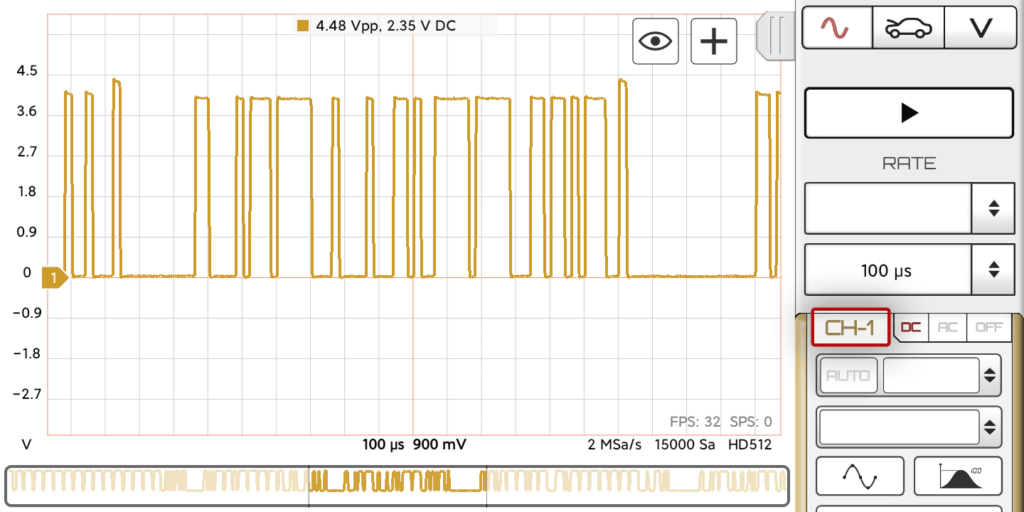
CAN (Controller Area Network) Bus is a serial protocol used in automotive and industrial machinery to allow microcontrollers to communicate with each other. It uses differential signalling (with signals named CAN H and CAN L) to increase noise immunity.
HScope can decode only the CAN-L signal.
Decoder Specifications
| Protocol | CAN 2.0 A and CAN 2.0 B (CAN FD not supported) |
| Signals | CAN-H |
| Max speed | Up to 1 Mb/s |
| Frame parameters | ID, DLC, Data bytes, CRC Sequence, CRC Delimiter, ACK Slot, ACK Delimiter |
Oscilloscope requirements
The oscilloscope sampling rate must be at least 3 times higher than the CAN speed. In case the CAN speed is 1Mb/s, you need to set the rate at least 3-4MSa/s.
Activating CAN Decoder
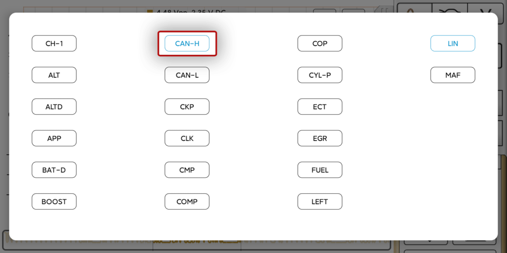
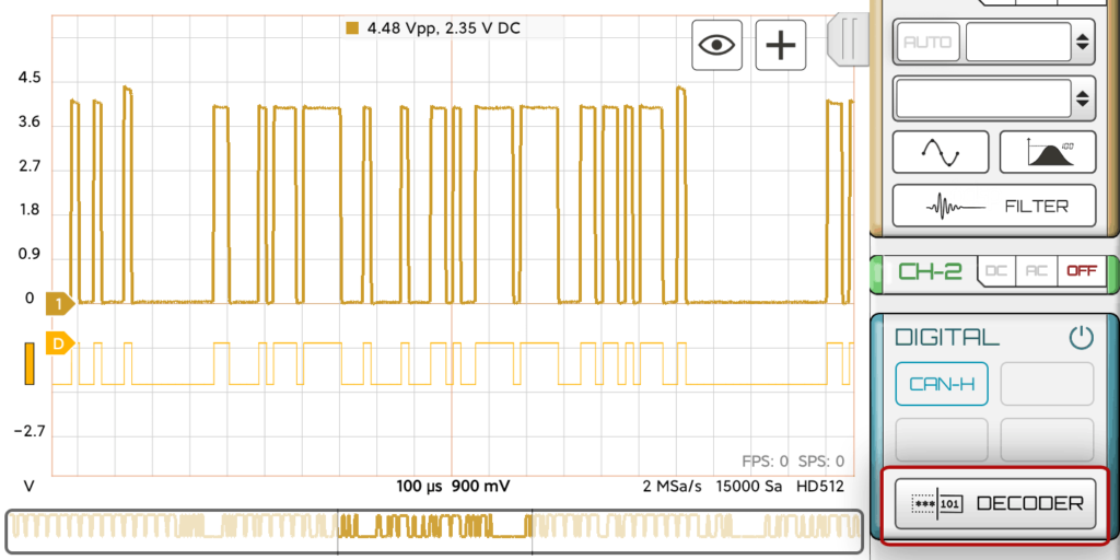
1. Assign the name to the channel that acquired CAN-L signal. This will create e digital signal in the Digital Module from the analog data.
2. Select the CAN decoder for the digital signal.
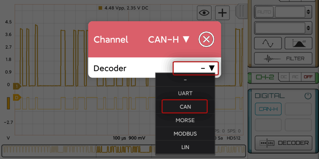
Now you should see the decoded data.
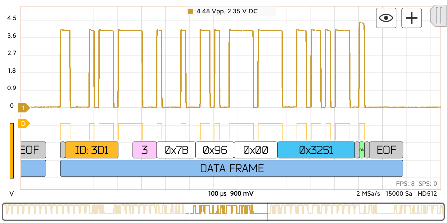
Fields: (all numbers in Hexadecimal format)
| Field name | Length (bits) | Purpose |
|---|---|---|
| Start-of-frame (gray) | 1 | Denotes the start of frame transmission |
| Identifier (yellow) | 11 | A (unique) identifier which also represents the message priority |
| Data length code (DLC) (pink) | 4 | Number of bytes of data (0–8 bytes) |
| Data field (white) | 0–64 (0-8 bytes) | Data to be transmitted (length in bytes dictated by DLC field) |
| CRC (blue) | 15 | Cyclic redundancy check |
| CRC delimiter (gray) | 1 | Must be recessive (1) |
| ACK slot (green or red) | 1 | Transmitter sends recessive (1) and any receiver can assert a dominant (0) |
| ACK delimiter (gray) | 1 | Must be recessive (1) |
| End-of-frame (EOF-gray) | 7 | Must be recessive (1) |