HS101-PRO Oscilloscope
HS101-PRO is an upgrated version of the HS101 Oscilloscope that joins the portability of an Android oscilloscope with advanced hardware features. The build require some experience with SMT mounting so approachable just from part of the DIY community. Within its specs, all the standard oscilloscope applications are possible with this device.
Specifications
-
Channels
1
-
Input Range
±1.5V to ±15V in 4 steps
-
ADC Resolution
up to 12 Bits (effective without noise: 9 bit, 10bit @ 100KSa/s, 11bit @ 75KSa/s, 12bit @ 12KSa/s)
-
Sampling rates
3KS/s to 1800KS/s in 13 steps
-
Bandwidth
(sine wave -3dB)Sine wave visible with sinc interpolation up to 400KHz @ 1800KS/s
-
Continous acquisition
Up to 100KSa/s
-
Input Noise
< 60mV (<= 15mV for Sampling Rate <= 100KSa/s)
<=20mV with the Black Pill (<=10mV for Sampling Rate <= 100KSa/s) -
Input Impedence
1MΩ
-
Input Coupling
AC/DC (hardware implemented)
-
Consumption
< 0.1A
-
Modules supported in HScope
Automotive Module, Audio Module
1. How to build it
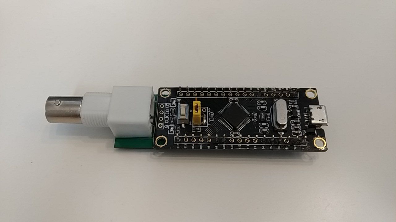
The hardware is based on STM32F103 microcontroller. It integrates 2 fast 12bit ADCs for the data acquisition. The Black Pill development board has been chosen for its low ADC noise among several development boards, so suiteable for this project.
Under this board we are going to install a little PCB module for input acquisition.
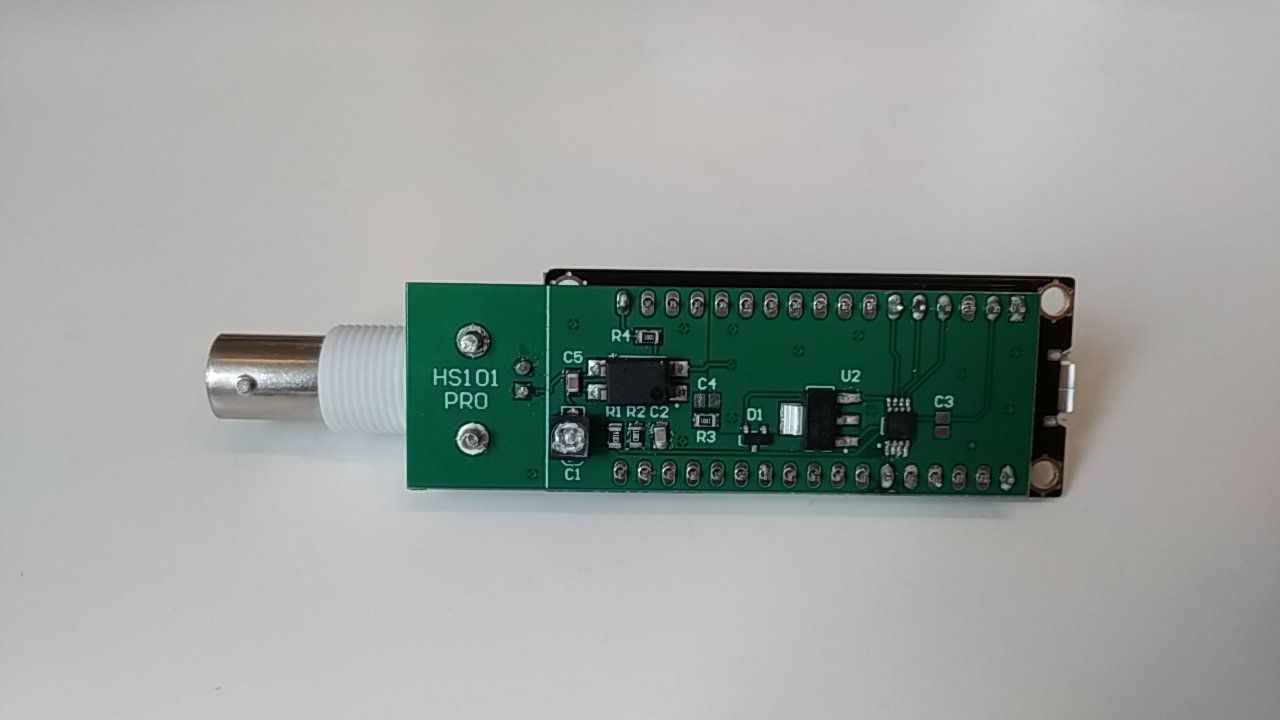
The input module includes the hardware AC/DC coupling and a variable signal amplifier with 1MΩ input. Here is the building scheme for this module.
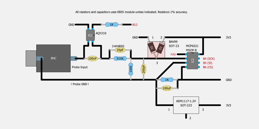
List of the components:
| Name | Value | |
|---|---|---|
| Microcontroller | STM32F103C8 Black Pill |  |
| Microcontroller Programming Tool | Raspberry Pi USB to TTL Cable (or another model specified here) | 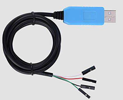 |
| PCB Board | Custom PCB | |
| SMT Components | All components in the schematic | USB Cable | USB OTG Cable - Micro USB to Micro USB or USB Type-C to Micro USB (according the device) | 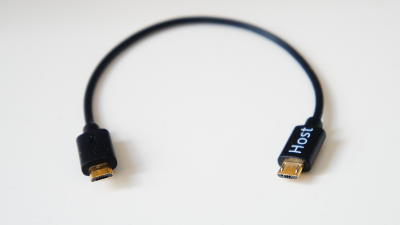 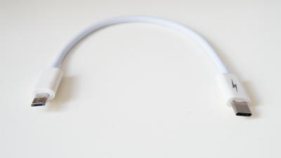
|
2. Flash the Firmware
You can get the firmware from GItHub (Version V10.1 or up)3. Calibration
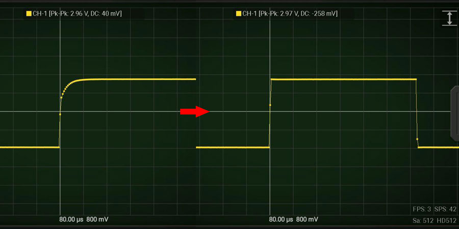
Beside the standard calibration in HScope this device require to calibrate the respose in frequency through the variable capacitor.
Procedure:1. When the oscilloscope is connected go in HScope Settings,
General - Hardware. Here Enable the Reference Signal. With this settings the HS101 will generate a square wave on pin B8.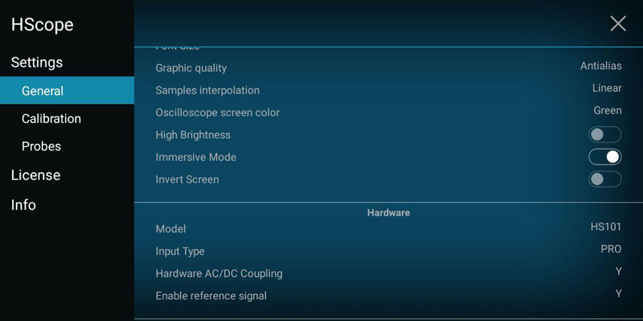
2. Connect the probe to pin
B8 so to acquire the Reference Signal. Use an high rate, i.e. 450KSa/s.
3. Turn the variable capacitor until the rising part of the square wave reproduce a good square. Now the device is calibrated in frequency response.