1. HS102 Oscilloscope Build Instructions
The hardware is based on STM32F103 microcontroller. Both 12bit ADCs are used for the data acquisition. The Blue Pill development board has been chosen for its size, suiteable for this project.
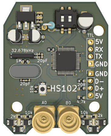
Over this board we are going to install a little module for input acquisition.
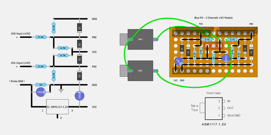
The input module is the only part that needs to be built with a stripboard. Here is the building scheme for this module. Components are on the top, connections are made on the back.
List of the components:
| Name | Value | |
|---|---|---|
| Microcontroller | STM32F103C8 Blue Pill | 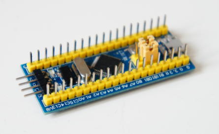 |
| Microcontroller Programming Tool | Raspberry Pi USB to TTL Cable (or another model specified here) | 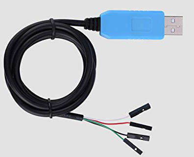 |
| Perforated PCB Board | 13x7 holes | 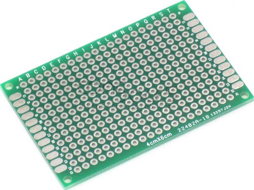 |
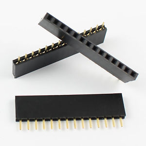
| Connectors | 6 Pin single row female 2.54mm pin header connector strip (x3) 14 Pin single row male 2.54mm pin header connector strip (x2) |
 |
| Resistors | 4.7KΩ - 1/4W (x4), 5.1KΩ - 1/4W (x2), 1KΩ - 1/4W (x1) | Diodes | 1N4007 (x4) |
| Capacitors | 100uF (voltage not relevant, x2) | |
| IC | ASM 1117 - 1.2V | |
| USB Cable | USB OTG Cable - Micro USB to Micro USB or USB Type-C to Micro USB (according the device) | 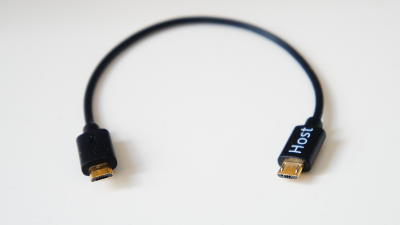 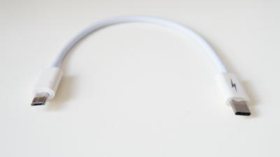
|
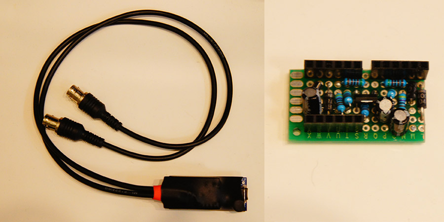
| Other | Probes with BNC Connectors or cable for making the probe. Plastic box or 40mm Heat-shrink tubing for boxing. |
Probe:
When using a BNC connector it is possible to use commercial oscilloscope probes. As an alternative it is possible to use a self made cable with or without connector (I suggest a shielded cable like a headphone cable).
2. Modifications to the basic schema
It is possible to design the analog input module to work with input voltage ±15V, or it is possible to add harware AC/DC coupling. You can check it here.
3. Flash the Firmware & Configuration
The firmware flashing is made with the app STM32 Utils which allow the direct flashing of the HS102 firwmare. In this app there are the instructions on how to connect the USB-TTL Cable to the STM32 Blue Pill board.
After the connection:
1) Go to Init Chipset and check that the app read the chipset
2) Go to the Blue Box icon and in the list select HS10X Oscilloscope, then FLASH FW
After flashing disconnect the USB-TTL cable from the STM32 board and reset the jumpers to the original position.
Firmware also available on GitHub
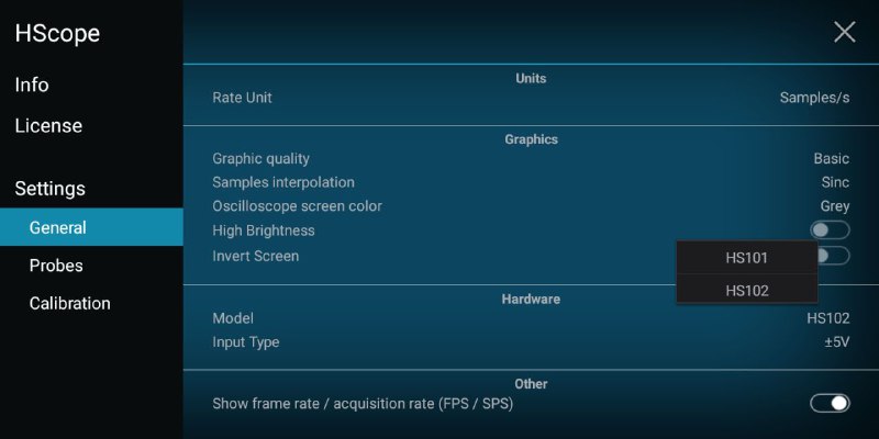
After installing the firmware, connect the HS102 to HScope and go in Settings->General->Hardware. Here select Model HS102 and ±5V for Input Type. Disconnect and reconnect the device to get the new hardware configurations.
4. Calibration
This device requires calibration since the built and the components could be sligthy different. After having connected the HS102 go to Settings->Calibration. Connect the probe to its GND and click on Calib Zero Lvl, first for Channel 1 and then for Channel 2.
After connect Channel 1 to an indipendent and stabilized 5V source. Click on Calib Multiplier and select Channel 1 and 5V as voltage reference. Confirm the operation and repeat also for Channel 2.
Now the device is calibrated.
5. Tests
The STM32 uses the USB power to work. Once connected to the phone the red led of the Blue Pill board should turn on. Opening the HScope app it should recognize the oscilloscope and show the data.
The free-version of HScope allows you to use the HS102 as a voltage tester and as a simple oscilloscope. Sampling rate and refresh rate are limited in the free-version.
With the full version of HScope it is possible to have access to real-time statistics, FFT, 2 Channels, XY Plot and to use the data logger. The refresh rate is up to 20-25 FPS.
6. Alternative Design
This is a full PCB implementation for range 0-20V by Vladimir (source files are available on Github):
7. Other
First Release: Nov 2018
Last Update: Jun 2019