1. HS10X Custom Oscilloscope
You can design your own oscilloscope hardware with several hardware design options, using the same HS10X Firmware. After you build your custom hardware you can just set some option in the Firmare with HScope and have your custom oscilloscope working.
You can implement your oscilloscope using 1 or 2 channels. For each channel you must build an analog input stage to adapt the input signal to the STM32 analog input which is 0-3.3V range. The analog input stage of each channel is composed of these parts:
- Probe BNC Connector
- AC/DC Coupler (optional)
- Voltage Divider with Overvoltage Protection (it convert the input range to 0-3.3V, suiteable to the STM32)
2. Number of Inputs
You will build one analog input stage for each channel (1 or 2), one identical to the other. Here is where these input stage should be connected to the STM32:
- Channel 1: PA0
- Channel 2: PB0
In HScope Settings -> General -> Hardware you can set the HS10X Model to HS101 and HS102 for respectively the 1 Channel or the 2 Channels version.
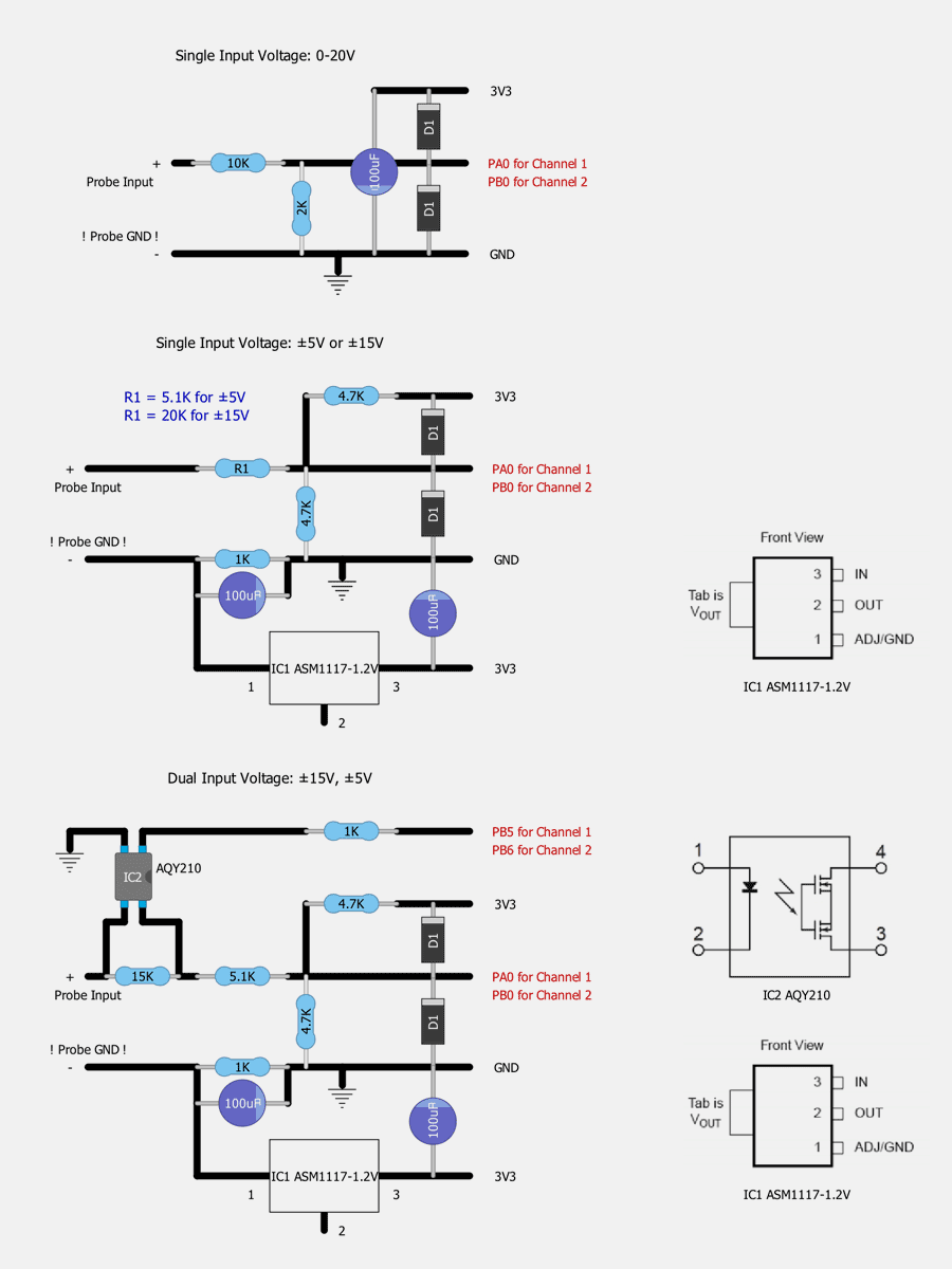
3. Voltage Range
Here are the schematics to make your oscilloscope with one of the following input ranges:
0-20V (single range)
±5V (single range)
±15V (single range)
±5V and ±15V (dual selection within app)
In HScope Settings -> General -> Hardware you can set the range you used. For dual voltage range you have to select DUAL.
4. Hardware AC/DC
It can be implemented by using this simple circuit (for each channel).
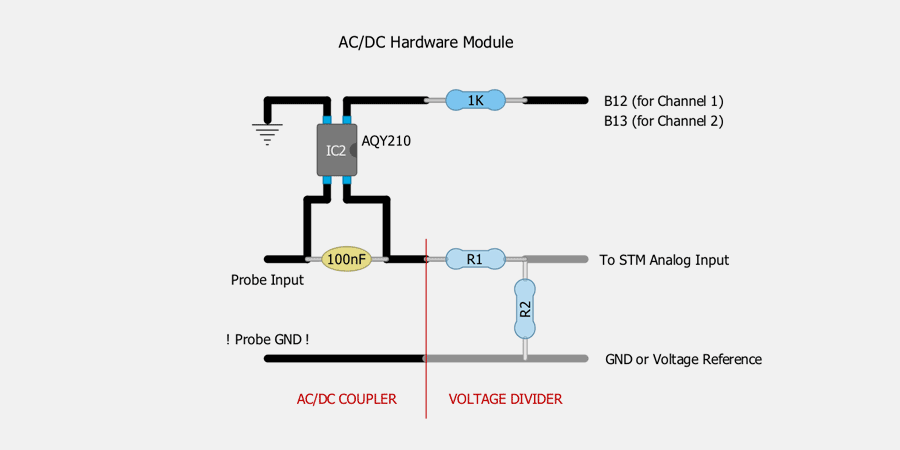
In case you use this circuit you need to set the Hardware AC/DC coupling option in HScope (Settings-General->Hardware) the first time after the device is connected.
Differences between hardware and software AC/DC Coupling
Oscilloscope hardwares has always DC Coupling, that means that both AC and DC components of the signal are recorded by the oscilloscope. AC coupling can be implemented by the hardware or it can be emulated in HScope app.
Hardware AC Coupling. When an oscilloscope has hardware AC Coupling (and when used) then the DC component of the signal is cut off. This works at every sampling rate and allows to view even small AC components of a high DC voltage, even if it exceeds the Input Range. For example if an oscilloscope has an input range of ±1V. We want to measure an AC ripple of ±0.5V on a 12V DC signal. With the hardware AC coupler we can see this ripple with good details on the oscilloscope with ±1V range.
Software AC Coupling. When an oscilloscope doesn’t have hardware AC Coupling and the HScope app uses the AC coupler emulation then the app calculates the DC component of the signal and subtracts it of the original signal. In this way just the AC component is shown. This method has the following limitations:
1. The signal range should always be within the oscilloscope input range. Otherwise part of the signal will be cut off (and the AC component will be lost). Because of this the oscilloscope should always use a greater input range than that required just for the AC component. This bring a loss in resolution in case the oscilloscope has lower input ranges, since these cannot be used.
2. The AC software coupler cannot be used in roll mode (at low sampling rate).
4. Bluetooth module
It can be implemented just for HS101 (standard, with different hardware modules and PRO version). All the information has been moved here.
5. Noise Considerations (valid only for Blue Pill board)
The noise is strongly dependant from the phone model. Here there is a list of tips to decrease the overall noise. More of these modifications are applied and lower is the noise:
- Add 2 capactitors between GND and 3.3V pins (there are 2 places on the Blue Pill. Value 100uF. The capacitor near the USB connector can be 470uF and this show a little improvement.
- Insulate the USB shield from the board GND. In some phone the USB shield is not connected to the GND of the phone so it generate noise. The 4 pins on the side of the USB need to be cut and USB connector need to be fixed in other ways that allow insulation from the board GND.
After these modification the +-5V module show an avarage noise at rest level (probe not connected) of 7mV @ 100KSa/s (max 10mV). On another phone this same hardware configuration show a noise of 10mV (max 12mV).
Noise at higher sampling rates is higher, up to 30mV. 300KSa/s and 600KSa/s can show lower noise (down to 15mV stable for 300KSa/s and 10-15mV for 600KSa/s, depending on phones)
Black Pill board do not require any modification since it has already the lowest noise possible for STM32F103C8T6 MCU.
6. Other
First Release: May 2019
Last Update: Oct 2019