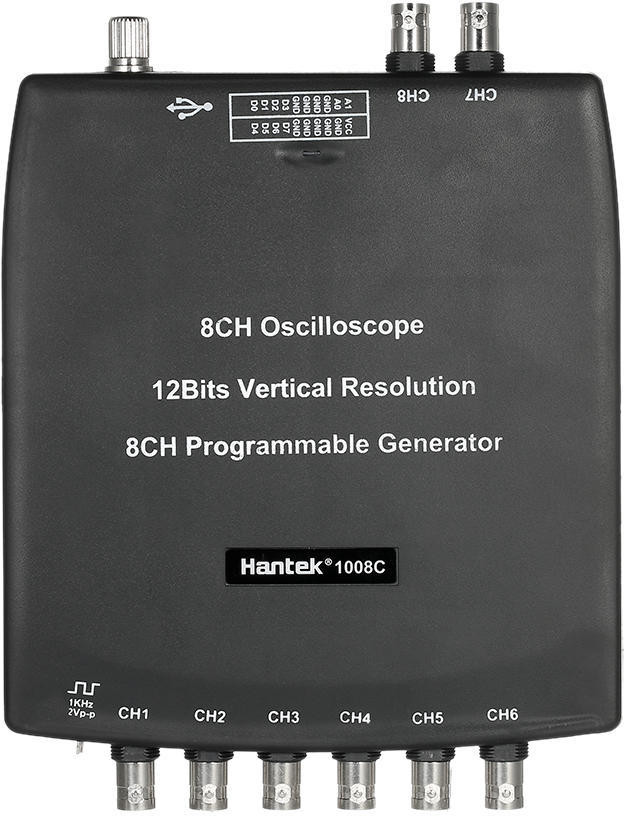
Specifications *
- Channels: 4 (from version 2.3.2)
- Effective ADC bits (without error): 9-10 bits
- Min sampling rate: 1 KSa/s
- Max sampling rate (2 channels): 1.2 MSa/s
- Input range: ±2.4V (not linear) and ±20V
- Number of samples each scan: 1000 Sa (2 Channels)
- Waveform update rate (2 channels, rate >= 100KSa/s): 30 wfms/sec
- Roll Mode: supported
- AC/DC: software emulation
- Power Consumption: < 10mA
Modules Support
- Automotive Module: supported up to 2KSa/s (for 2 Channels)
- Audio Module: NOT supported
Advantages
- High ADC resolution
- Wide input range
Disadvantages
- Low sampling rate
- Low real-time acquisition rate (for Automotive Module) up to 2KSa/s with 2 Channels
Additional notes
The 4 channels work from version 2.3.2 with a recent HScope license. In case you have a license older than 1 year (before Jan 2020) the 4 channels will be available just with the Update 2020 license or if you buy any other new license.
The trigger works just on Channel 1 and Channel 2.
The maximum rate and number of samples is split among the enabled channels. Once you set 2 or 4 channels enabled the list of rates get updated with the available values.
Specific Configurations
This device has specific configurations in HScope. It is possible to change Channel 3 and Channel 4 to be any other between Channel 3 and Channel 8. You can find these configurations under Settings -> General -> Hardware.
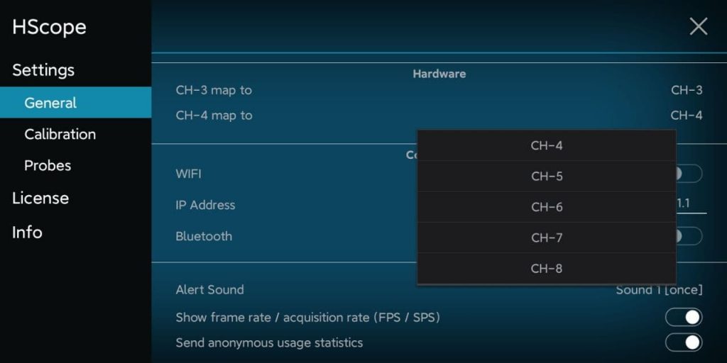
Note: this setting is allowed just if Channel 4 is set to another channel greater than Channel 3. For example you can set Channel 4 to be Channel 8 and then set Channel 3 to be Channel 6.
Hantek 1008 vs Hantek 6022
Input Voltage Range
The range ±20V is linear and the only suggested to use. In this range the oscilloscope has a noise around 40-60 mVpp.
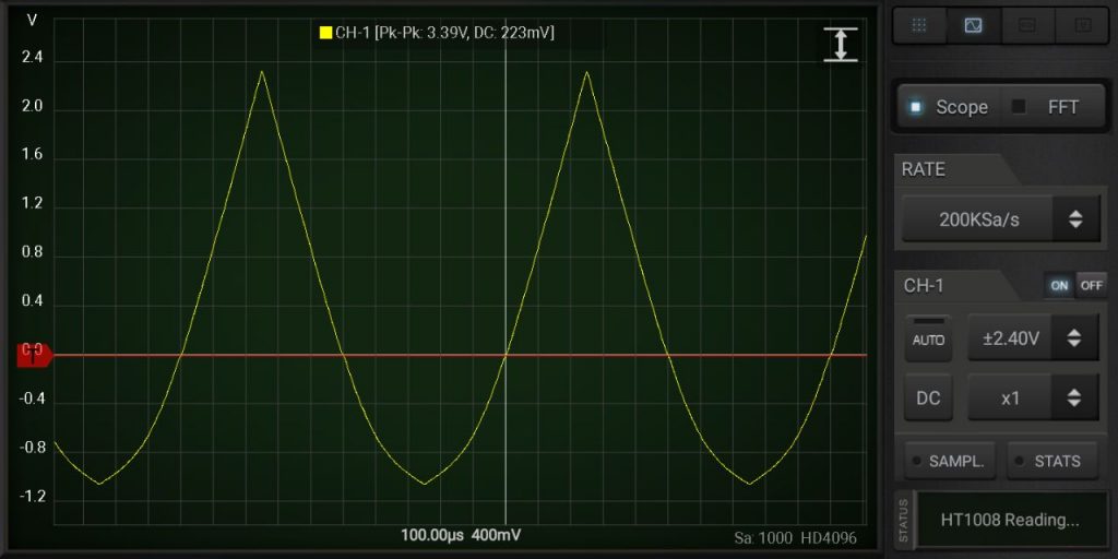
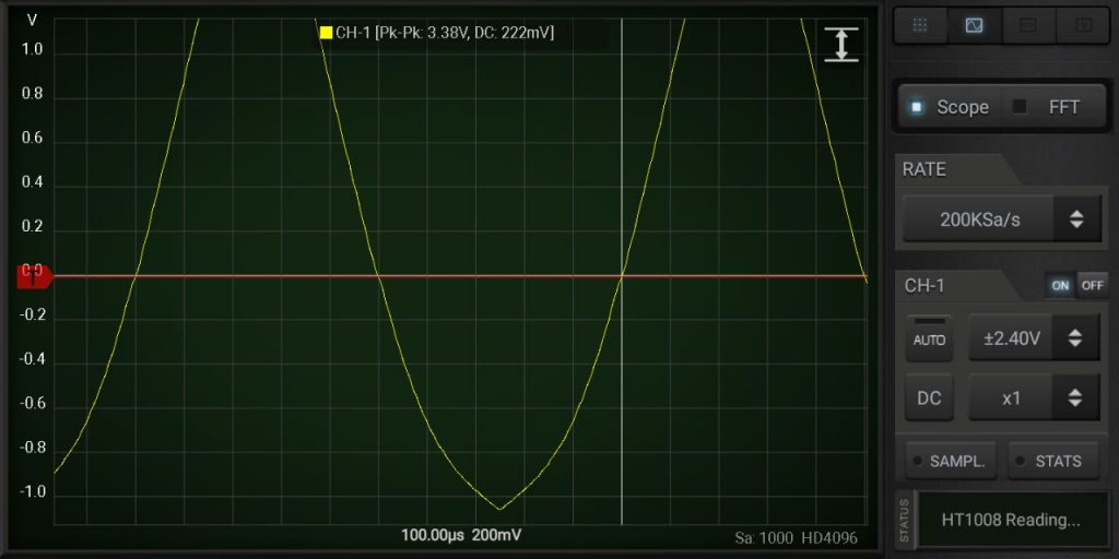
In case it is required to analyse much lower voltages then you can use the range ±2.4V that allow a minimum noise around 8 mVpp. The ±2.4V is linear just in the range -0.5V to +2.4V.
Test with a Triangle wave in the range ±2.4V:
Issues
Voltage Drift
The most relevant issue of this device is the voltage level drift over the time. The producer indicate to use the device after some minute from the power on to let it stabilize. On HScope it is require a regular calibration of the Zero Level on both channels to avoid errors up to 50mV on readings.
Related Videos
Other Resources
- Hantek 1008 Vendor Website
- Hantek 1008 on Sigrok