
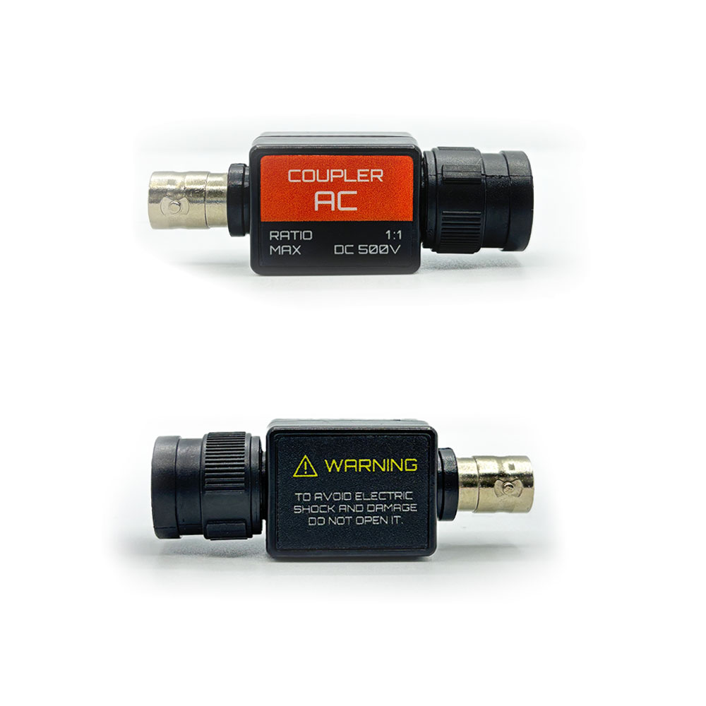
Description
By using this item, the oscilloscope can measure the voltage higher than its range. For example a standard oscilloscope with ±5V input range can read up to ±20V input range.
A special Spark version is designed for automotive use, i.e. fuel injectors and main point arc waveform, due to higher insulation properties.
It’s unique feature is the possibility of compensation that allow to be used with several oscilloscope brand and models (check the specifications).
Specifications
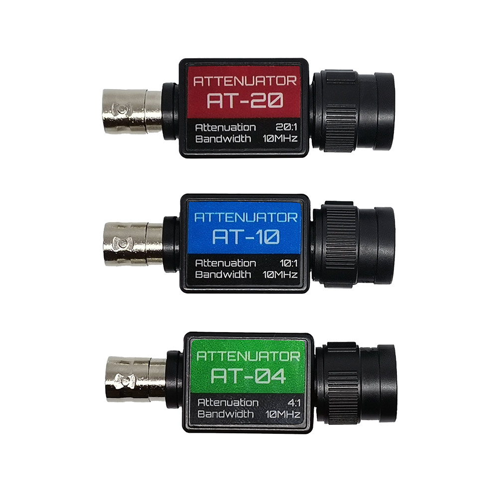
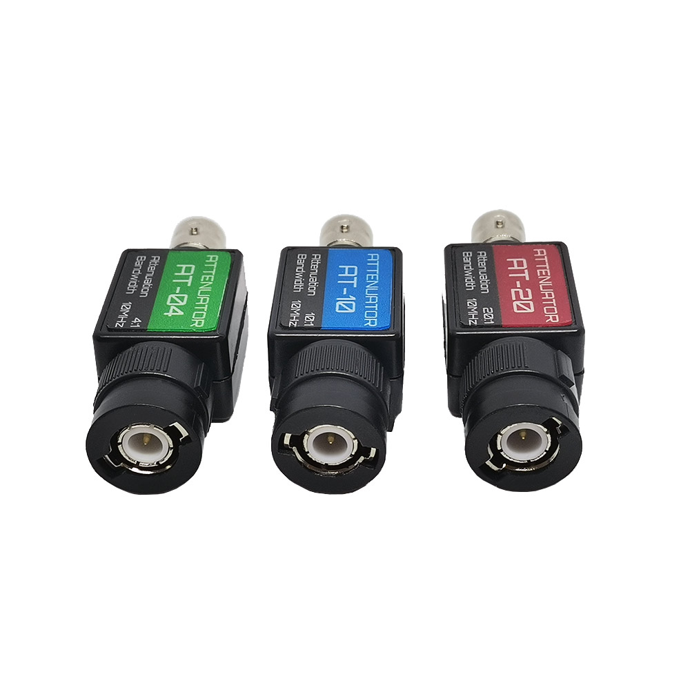
| SPARK | AT-20 | AT-10 | AT-04 | |
| Attenuation factor | 20:1 | 20:1 | 10:1 | 4:1 |
| Typical Use | Fuel injectors / Primary ignition |
Extend oscilloscope range from: ±5v to ±100v |
Extend oscilloscope range from: ±5v to ±50v ±16v to ±160v |
Extend oscilloscope range from: ±5V to ±20V ±16V to ±64V ±20V to ±80V |
| MAX Voltage | 500V (resists to 1000V spikes) | 100V | ||
| Compensation | ✗ | ✓ | ✓ | ✓ |
| Spark/ESD Protection | Output limited to 50V | Output limited to 50V | Output limited to 50V | ✗ |
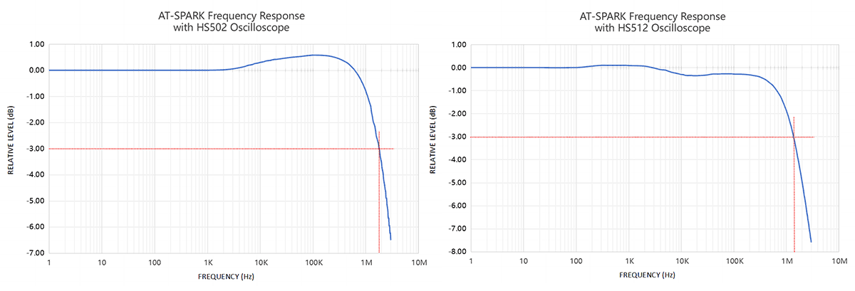
| Bandwidth | > 1 MHz (with HS502 and HS512) | 10MHz | ||
| Input Resistance | 1.06M | 1.06M | 1.13M | 1.50M |
| Compatibility | Supports different oscilloscope models with input impedance 1MOhm since it can be compensated according the oscilloscope model.
Tested on Hantek, Loto and HS oscilloscopes. |
|||
| Item Size | 60 x 21 x 16mm 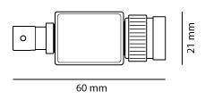 |
|||
Suggested Product for Oscilloscope
| SPARK | AT-20 | AT-10 | AT-04 | AT-AC | |
| HS512 MAX | X | ||||
| HS502 | X | X | X | X | |
| HS10X / HS402 DIY Oscilloscopes | X | X | X | ||
| Loto OSC482/OSC802/OSCA02/OSC2002 SainSmart DS802/DDS120/DDS140 Rocktech BM102 |
X | X | X | X | |
| Loto OSCH02 | X | X | X | ||
| Hantek 6022 Voltcraft DSO2020 |
X | X | X | X | X |
| Hantek 1008 | X | X | X | X | |
| Hantek 6074 | X | X | |||
| Fosc 53B | X | X | X | X | |
| Fosc 53C | X | X | |||
| Hantek iDSO1070 / Saluki MO1070 | X | X | X | ||
| Hantek DSO-2090/2250 | X | X | X | ||
| Instrustar ISDS205 | X | X | X | X | |
| Instrustar ISDS210 | X | X | X | ||
| Owon VDS1022 | X | X | X | ||
| Generic oscilloscope with 5V max input | X | X | X | X | |
| Generic oscilloscope with 20V max input | X | X | X |
Requirements
- Oscilloscope with input impedance 1MOhm, BNC connector.
- Regulation of compensation requires a square waveform between 1 and 10KHz.
Package Includes
- x1 piece attenuator
- x1 plastic screwdriver for the regulation of the compensation (for compensated models)
Quick Introduction
Note
Do not use this attenuator for high voltage measurement except fuel injectors or primary ignition. This attenuator must not be used to measure mains voltages, secondary ignition or other hazardous voltages.
Fuel injector and primary ignition signals contain short duration high voltage spikes “inductive kicks”. We therefore recommend the use of two ground connections between the oscilloscope and the vehicle under test. One ground connection is made using the measurement test lead. A second ground lead should be connected between one of the BNC connectors on the oscilloscope and a secure ground point on the vehicle such as the negative terminal of the battery. Misconfiguration and/or failure to follow these warnings may cause damage to the product and/or computer and could cause injury to yourself or others.
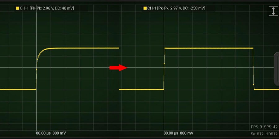
Compensation (AT-04, AT-10, AT-20)
This is the procedure to adapt your AT attenuator to your oscilloscope. This procedure is to be done just the first time you use the attenuator with your oscilloscope or when you use another oscilloscope. Check also the quick video introduction to know more.
- Connect the attenuator to one of your oscilloscope channel.
- Connect the channel with the attenuator to the oscilloscope reference waveform (square wave)
- Turn the compensation screw with the provided ceramic screwdriver until the waveform is a good square wave, like in the following picture:
AT-SPARK Frequency Response