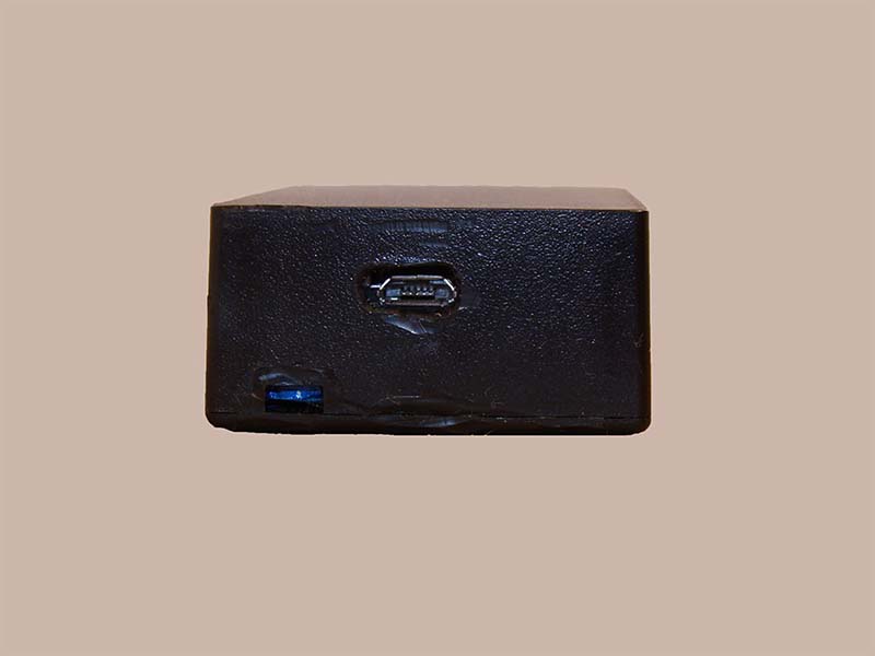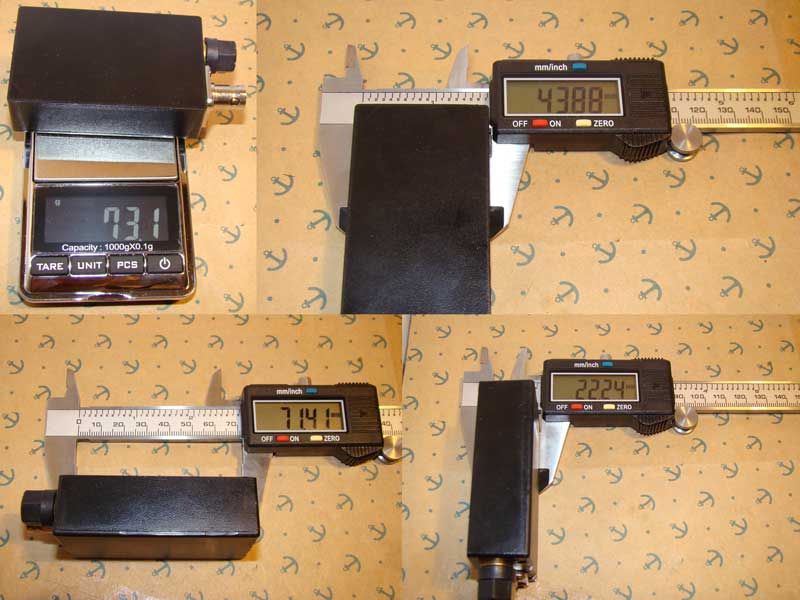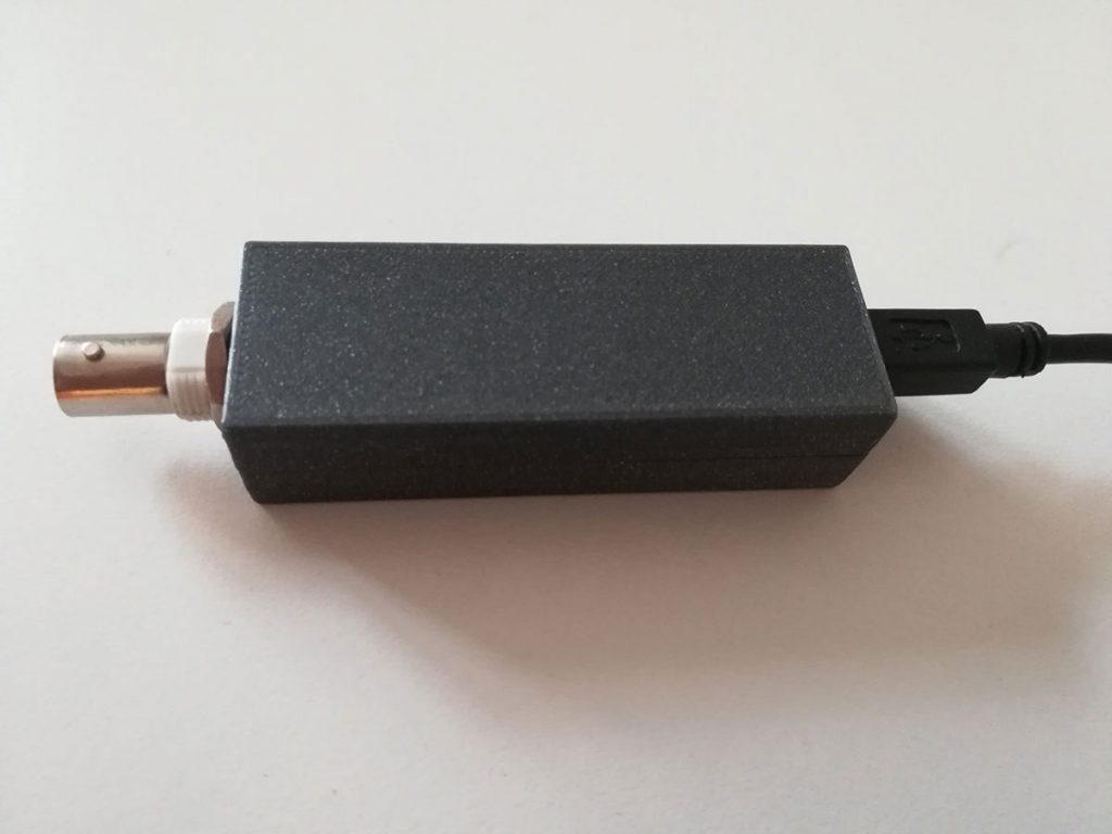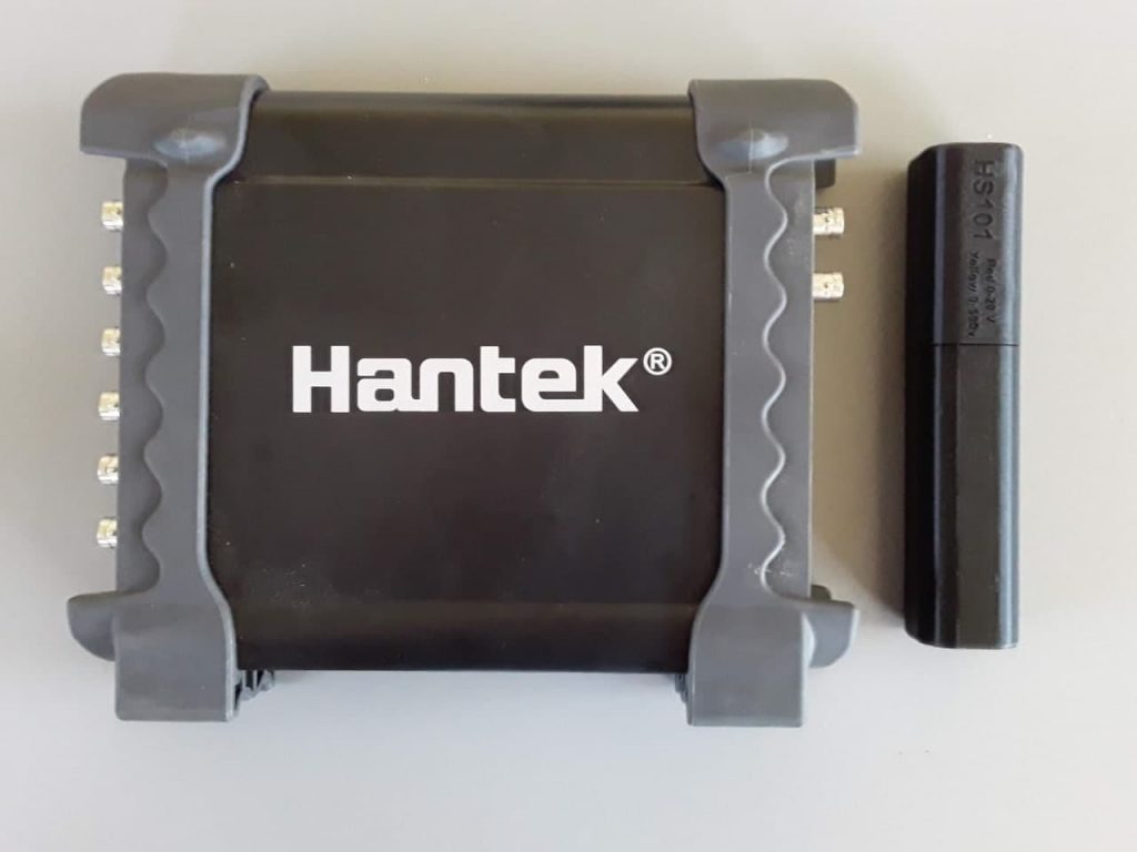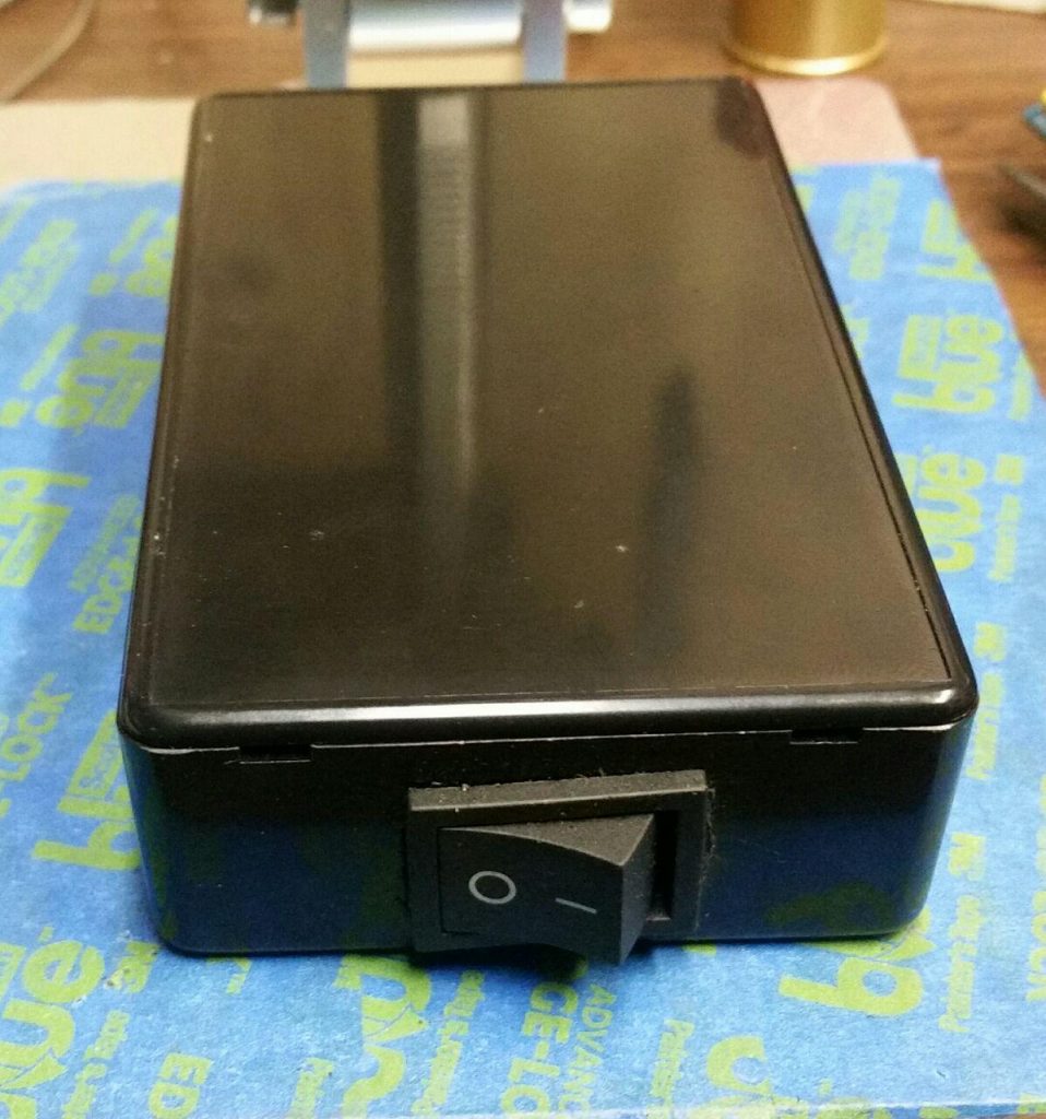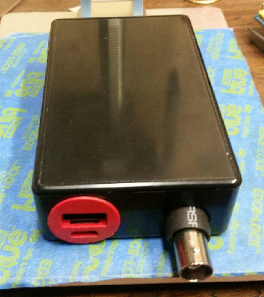
HS101 PRO DIY Oscilloscope
HS101-PRO is an upgrated version of the HS101 Oscilloscope that joins the portability of an Android oscilloscope with advanced hardware features. The build require some experience with SMT mounting so approachable just from part of the DIY community. Within its specs, all the standard oscilloscope applications are possible with this device.
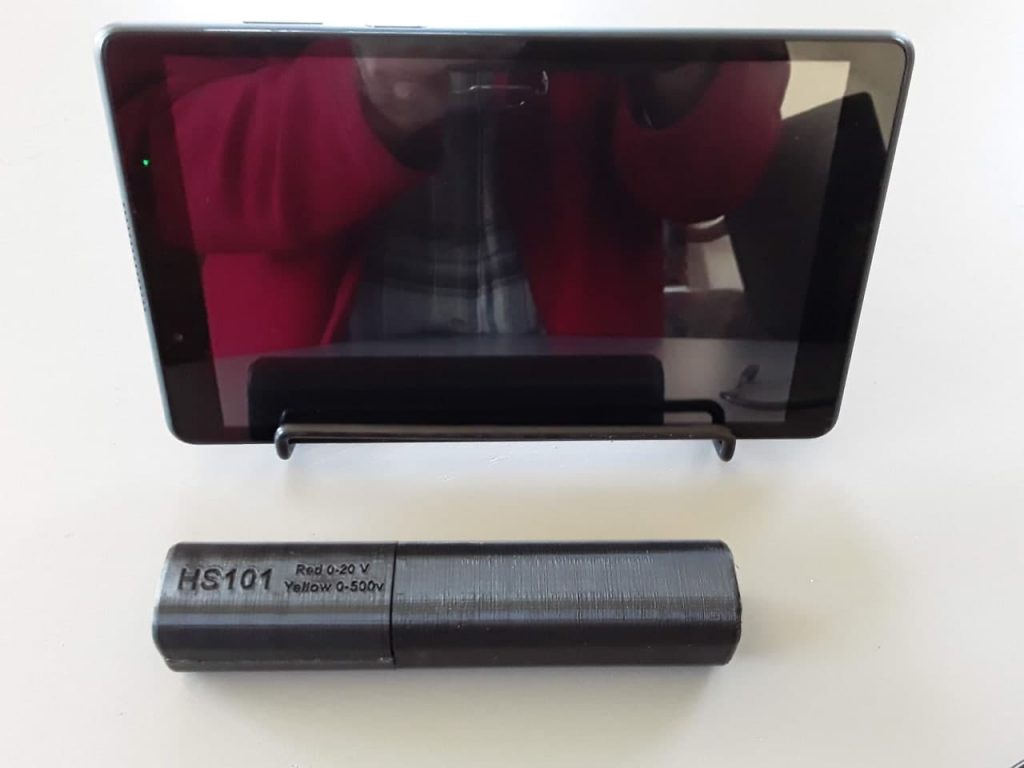
Power consumption is also one of the lowest in the market (~40mA). It can be used only with HScope app for Android.
HScope is in continuous development thanks to the suggestions from the users and the contributions of the supporters, and aim to become one of the best affordable high-tech diagnostic tool.
Consider to support HS10X project with a donation!

Intro
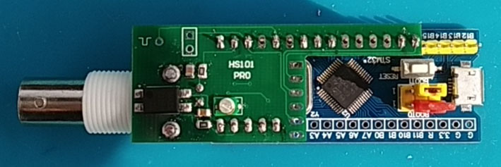
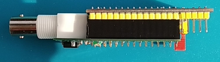
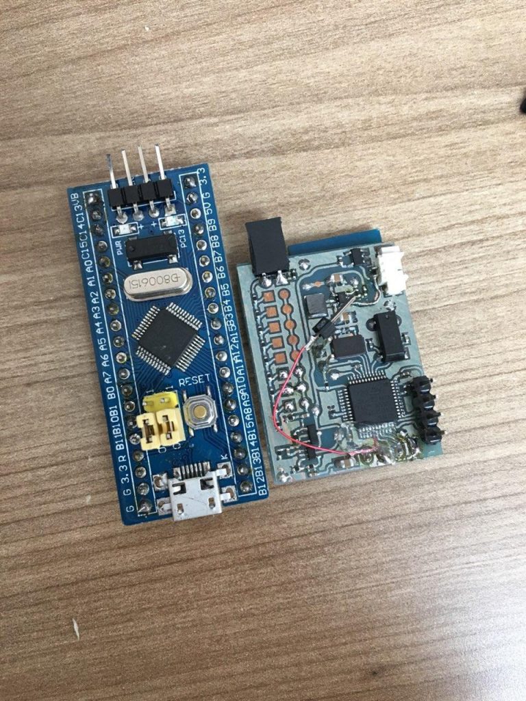
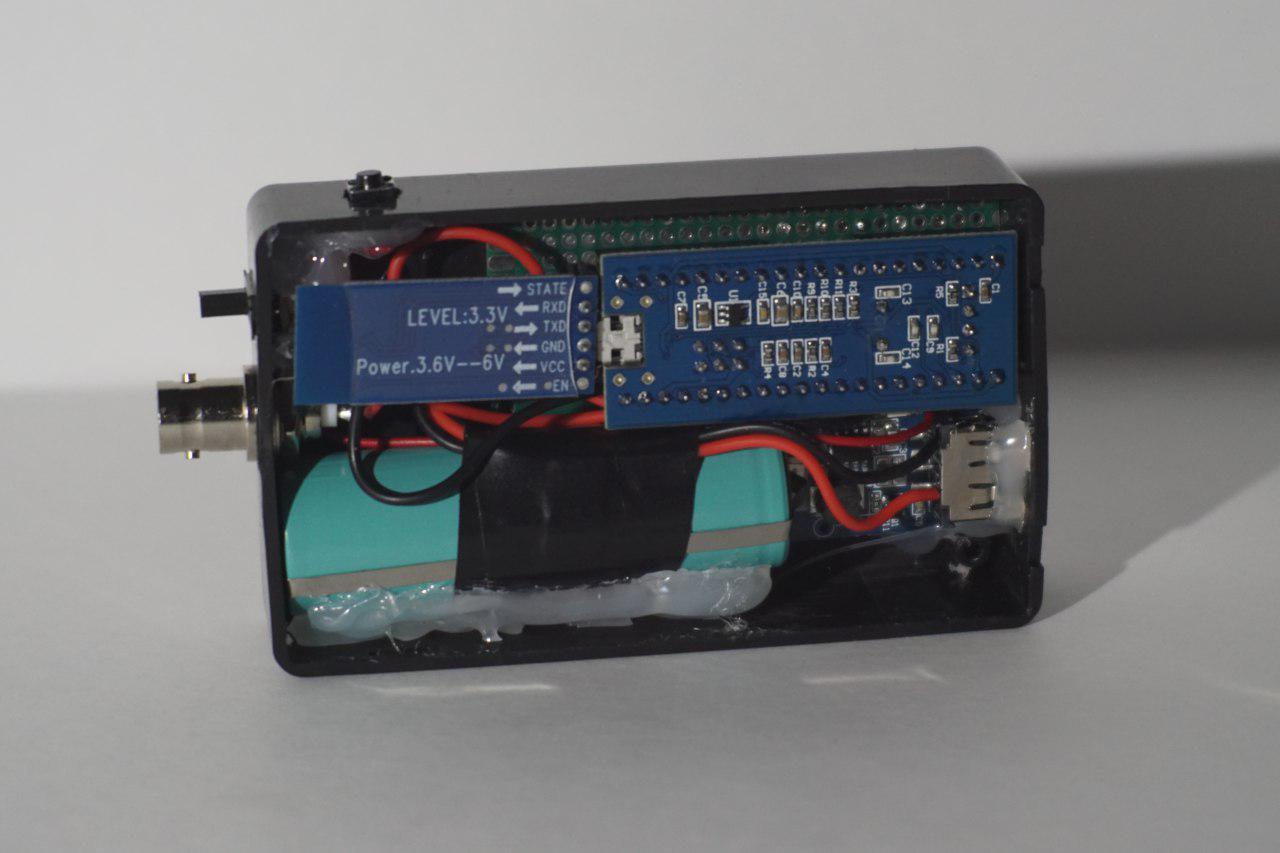
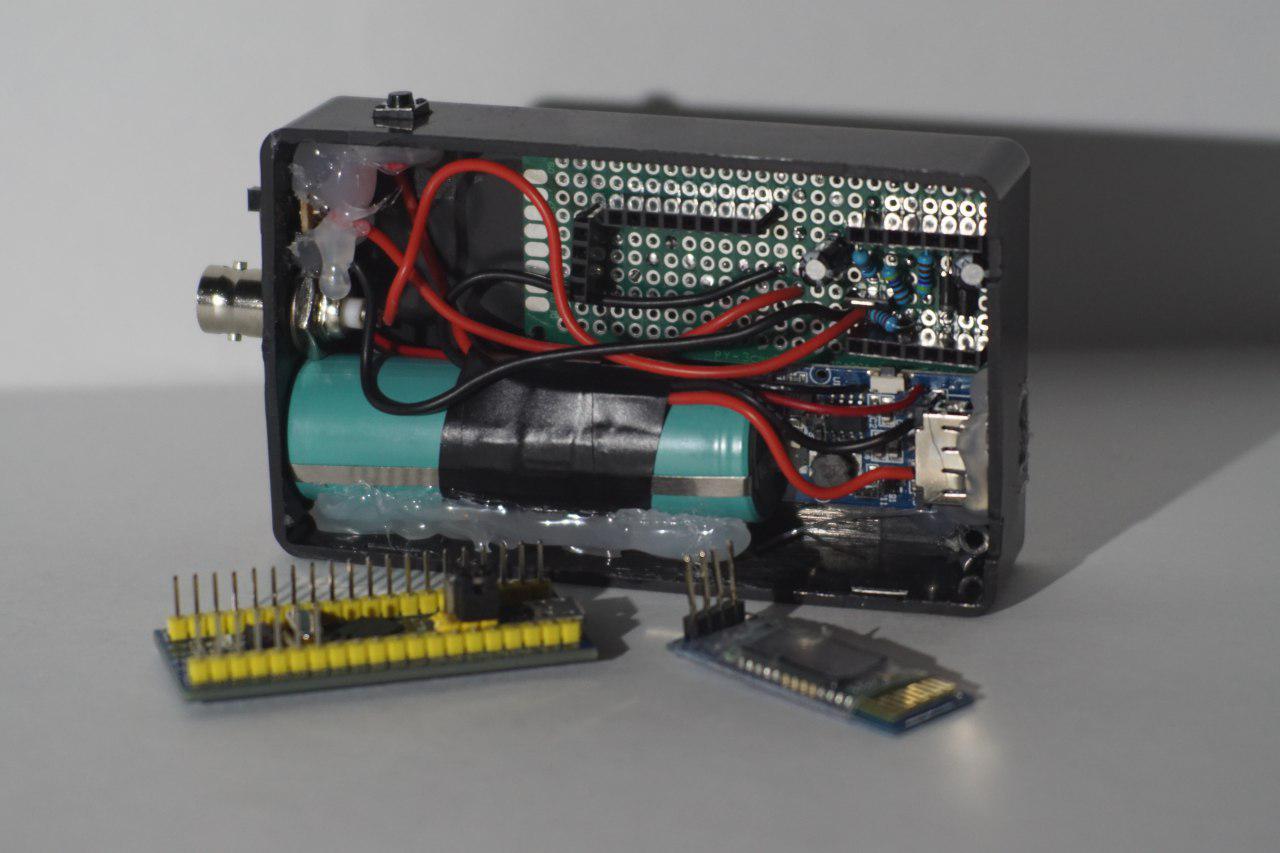
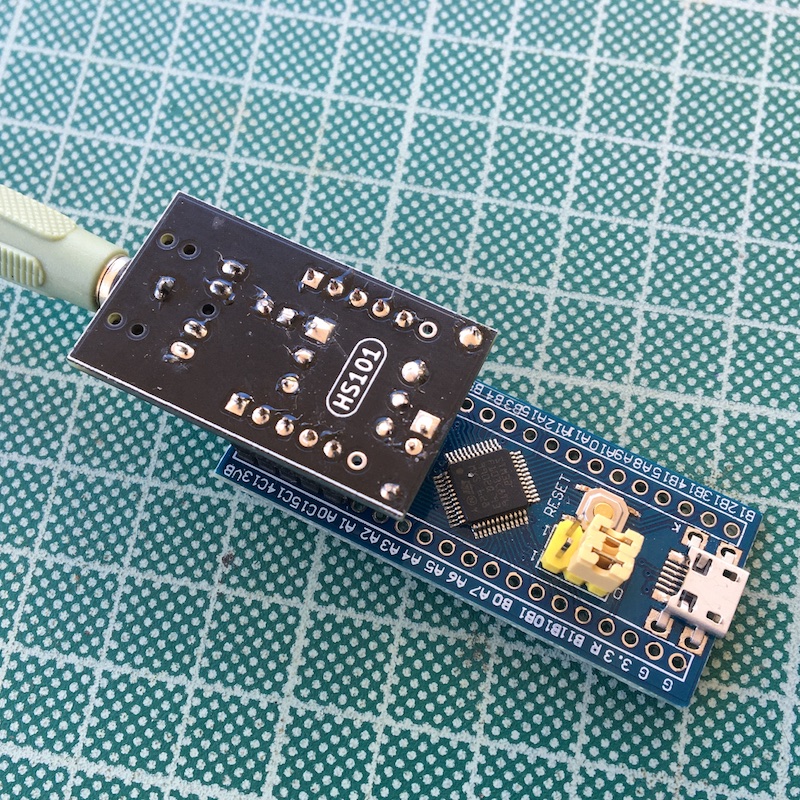
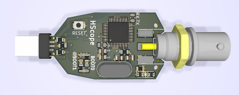
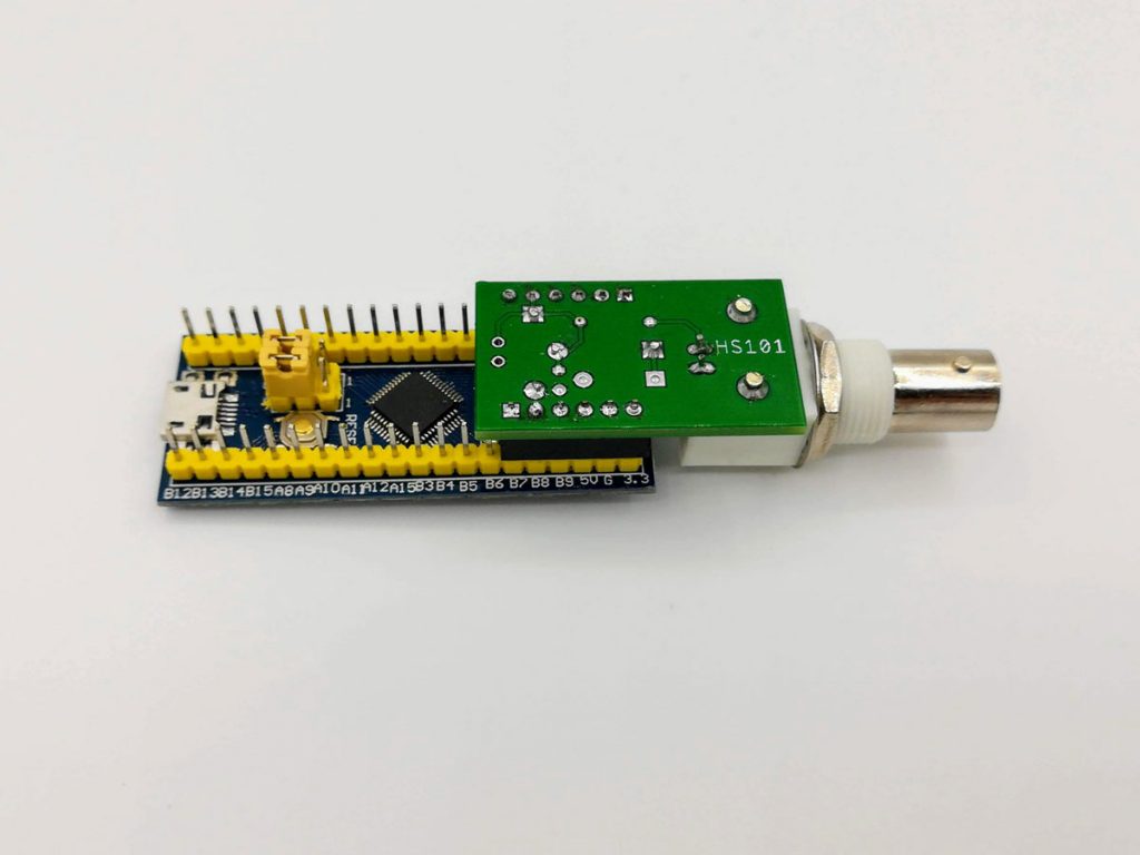
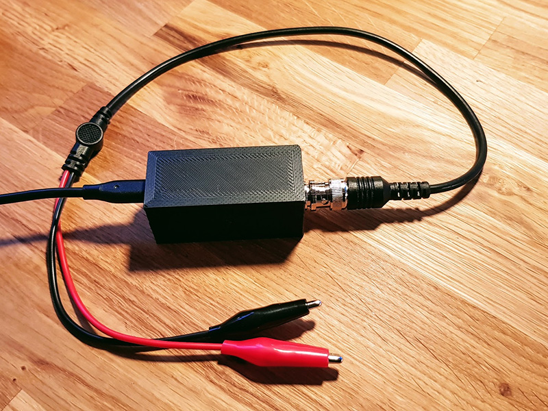
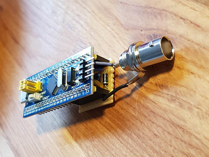
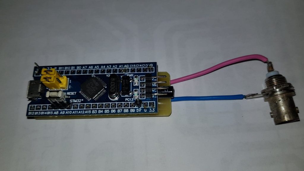
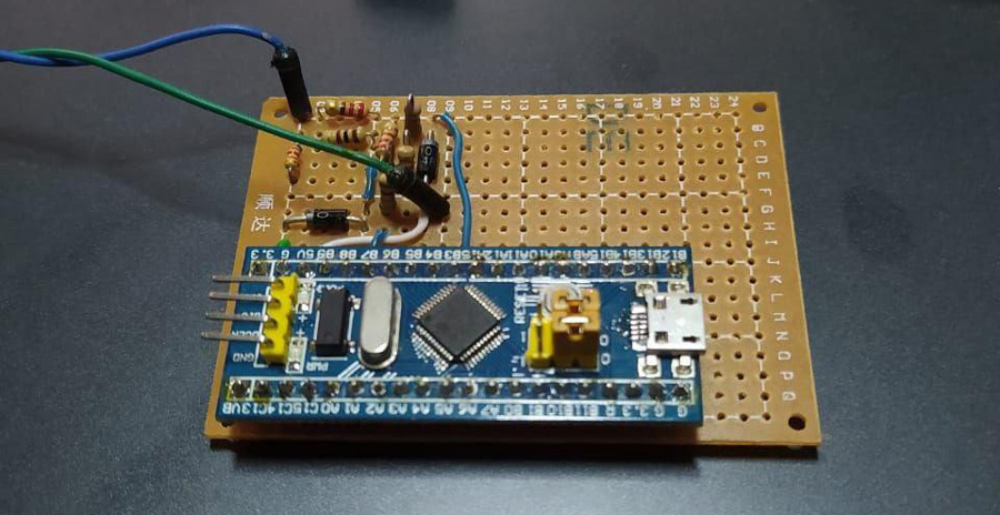
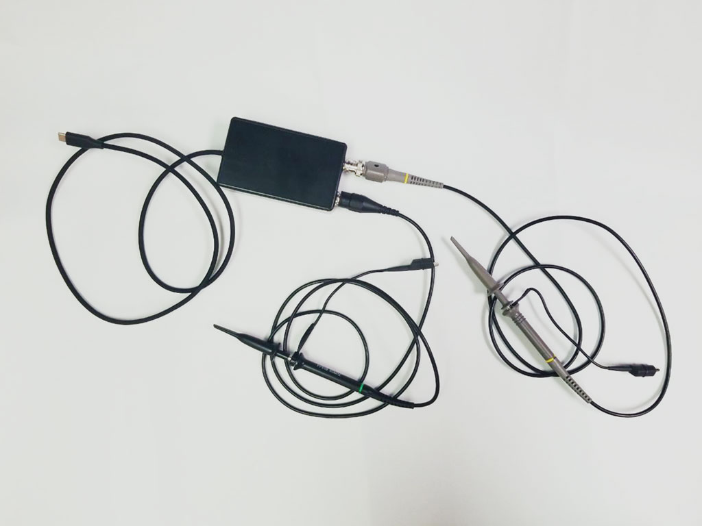
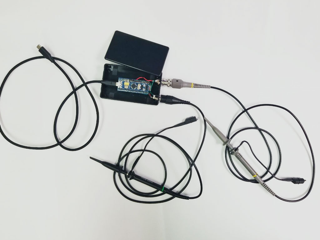
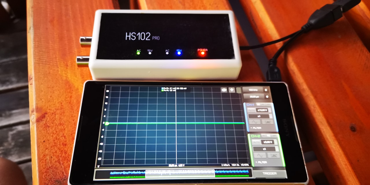
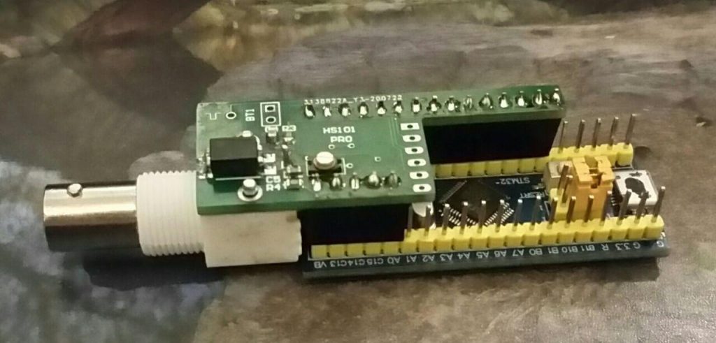
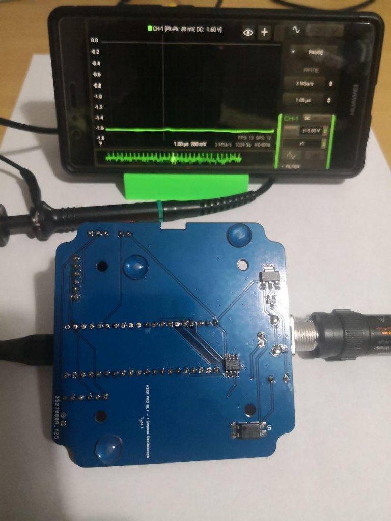
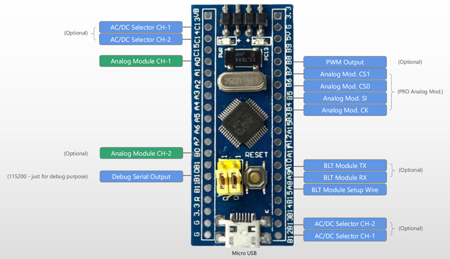
A Single Channel oscilloscope based on STM32F103 Blue Pill development board. It provide long memory buffer and high real-time transfer speed.
Technical Specifications
| Channels | 1 |
| Input Range | ±16V, ±8V, ±4V, ±1.6V, ±500mV |
| Sampling Rate | 2 KSa/s – 2,5 MSa/s |
| ADC Resolution | up to 12 Bits (effective without noise: 9 bit, 10bit @ 100KSa/s, 11bit @ 75KSa/s, 12bit @ 12KSa/s) |
| Input Noise | < 60mV (<= 15mV for Sampling Rate <= 100KSa/s) <=20mV with the Black Pill (<=10mV for Sampling Rate <= 100KSa/s) |
| Bandwidth | 600 KHz (max visible frequency with sinc interpolation @ 2.5MSa/s) |
| Input Impedance | 1 Mohm (1.010 kOhm) |
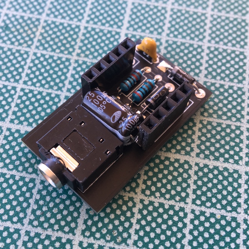
| HW Options Supported | – AC/DC Coupling Module – PWM Output Generator |
| Modules Supported in HScope | Automotive Module up to 100 KSa/s Audio Module PWM Generator: supported up to 1 MHz, duty cycle 1-99% |
| OS Version | Android 4.4+ |
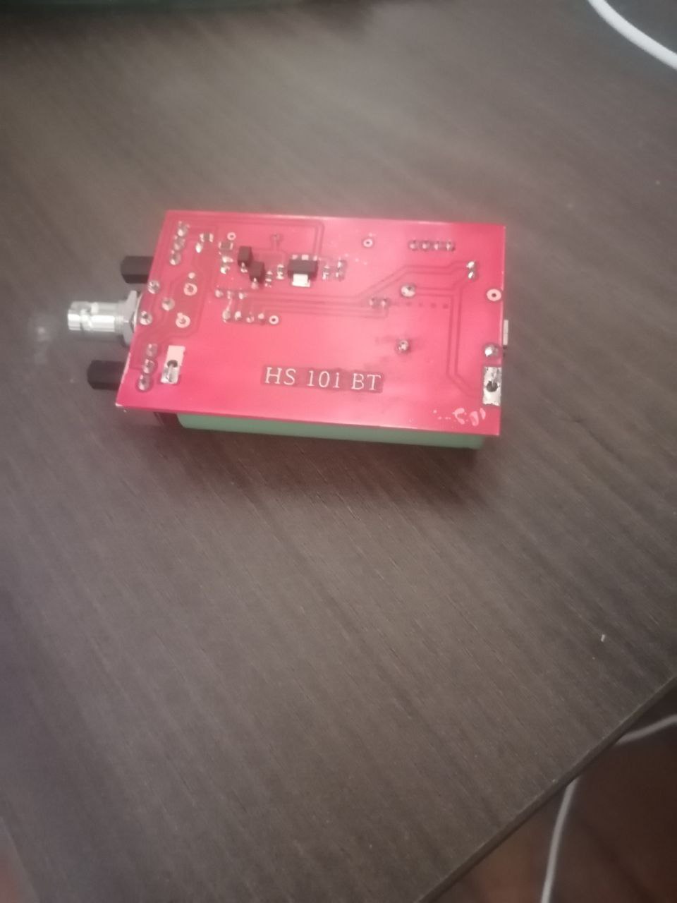
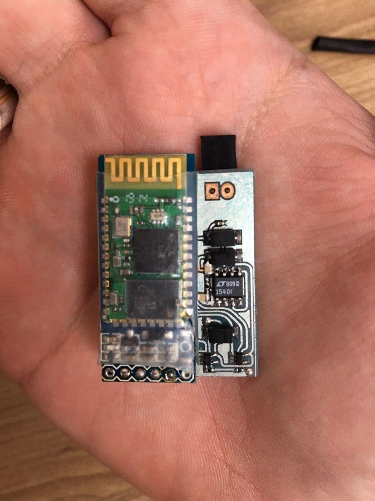
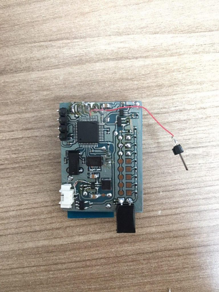
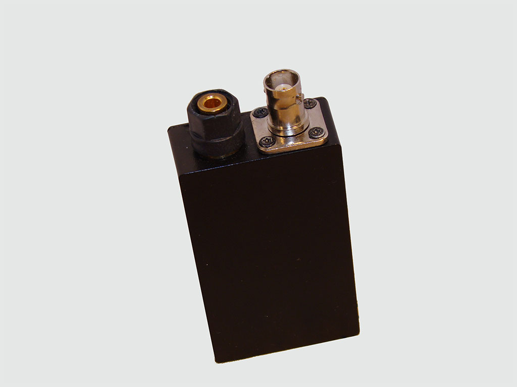
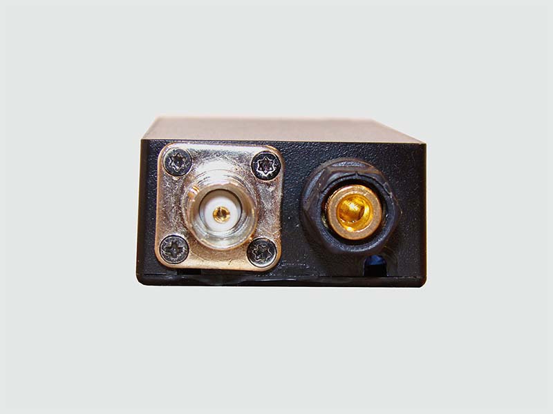
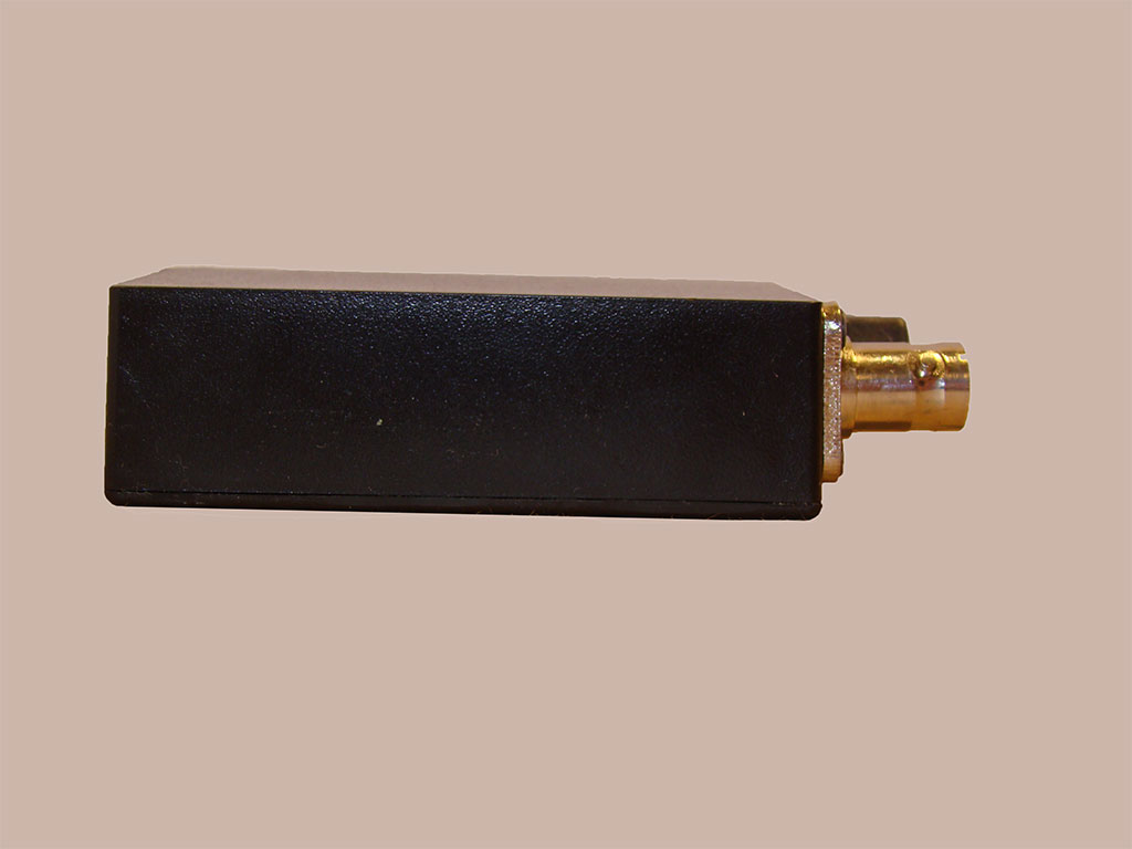
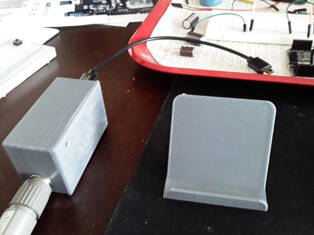
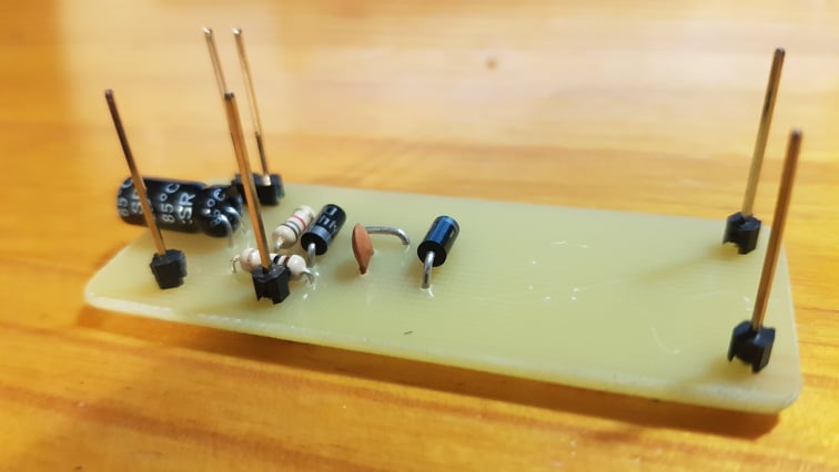
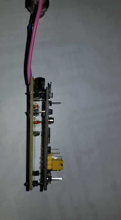
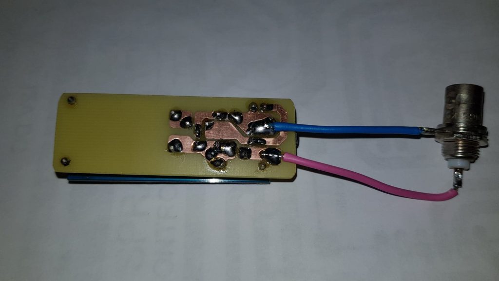
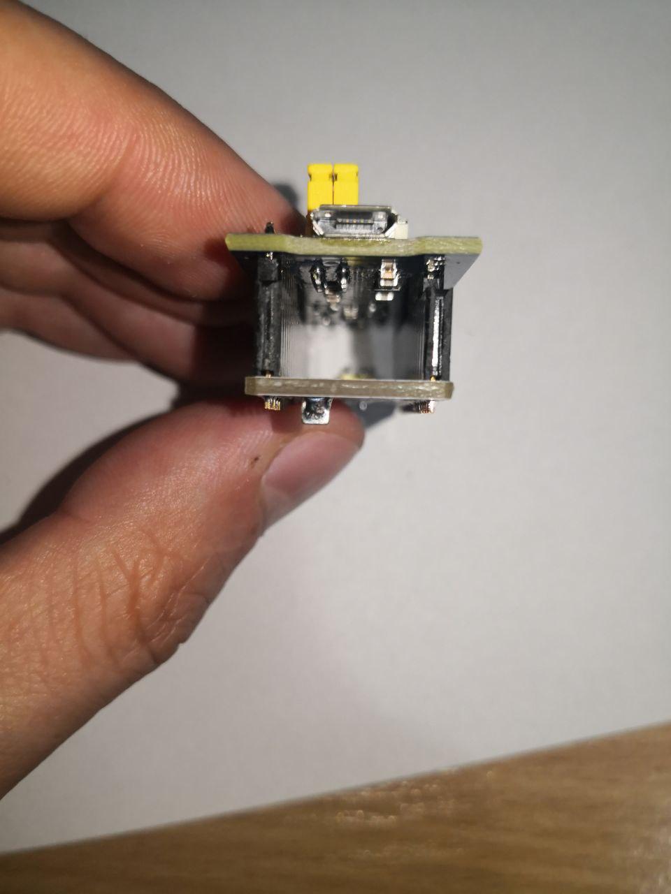
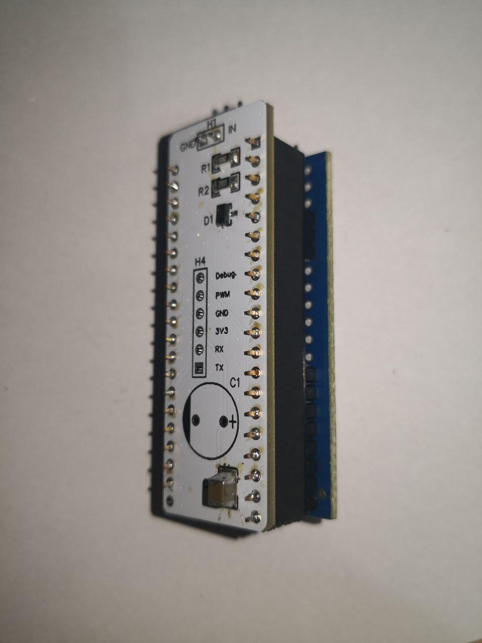
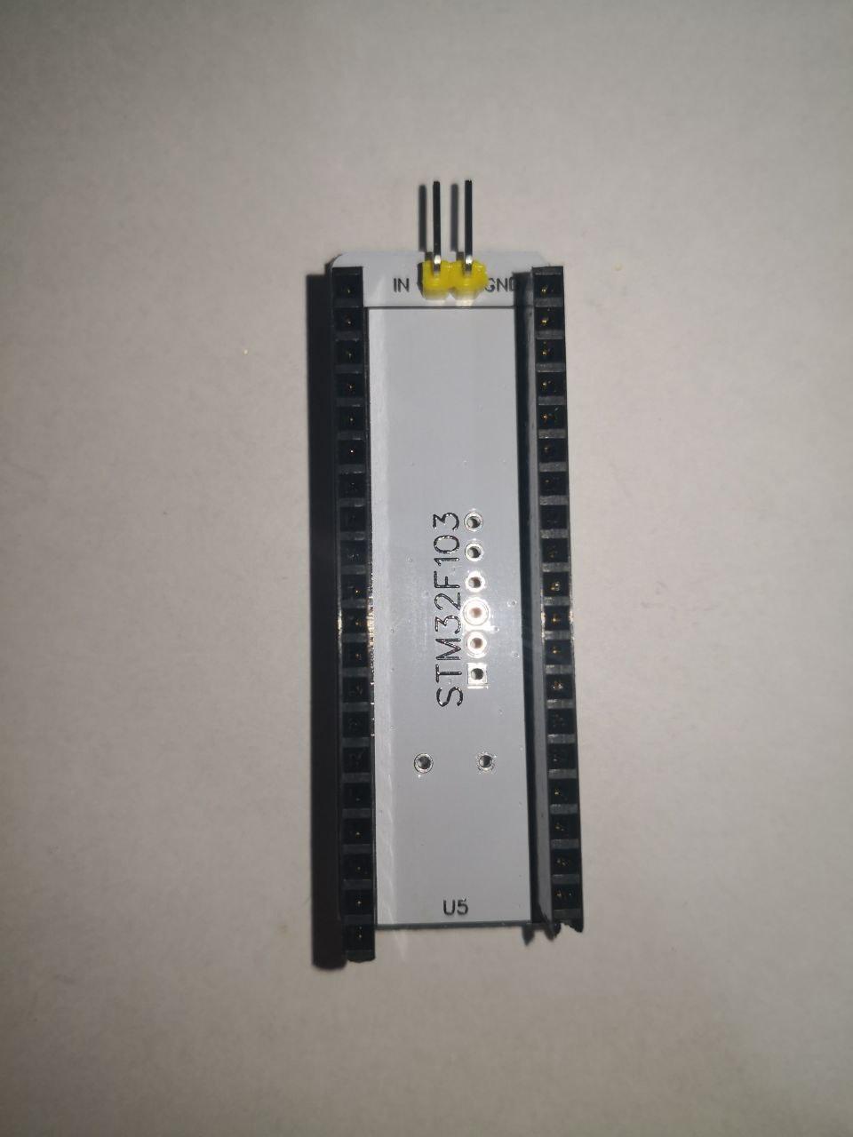
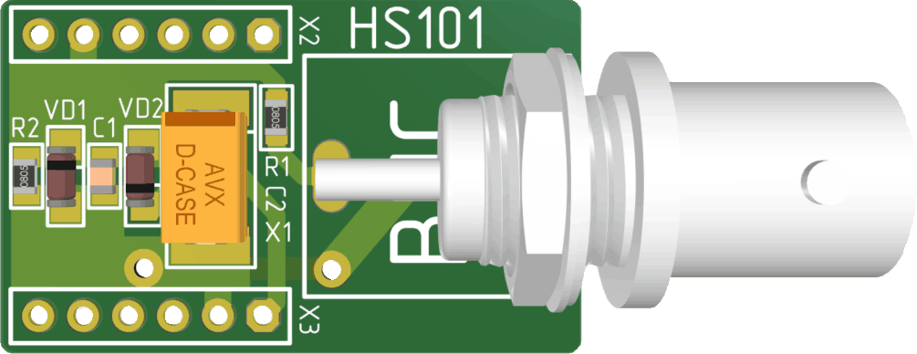
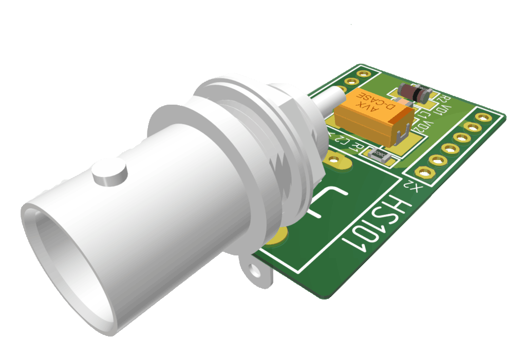
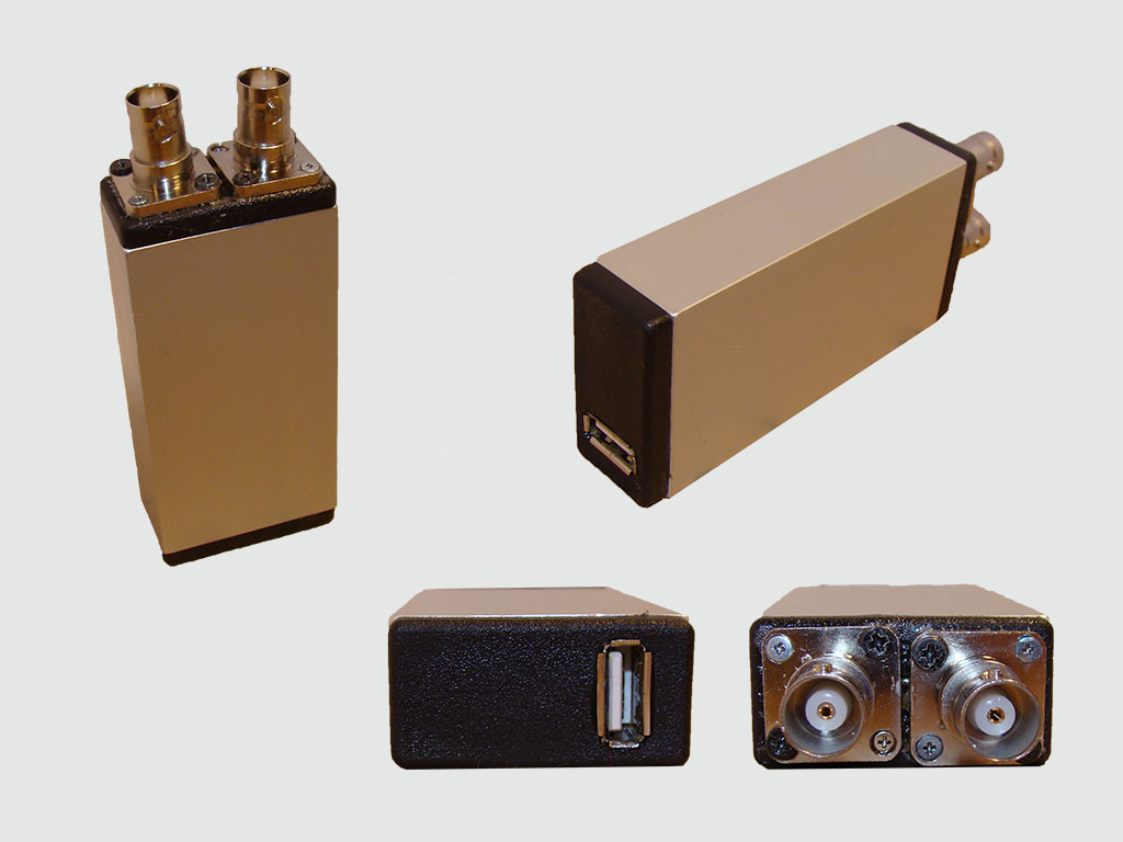
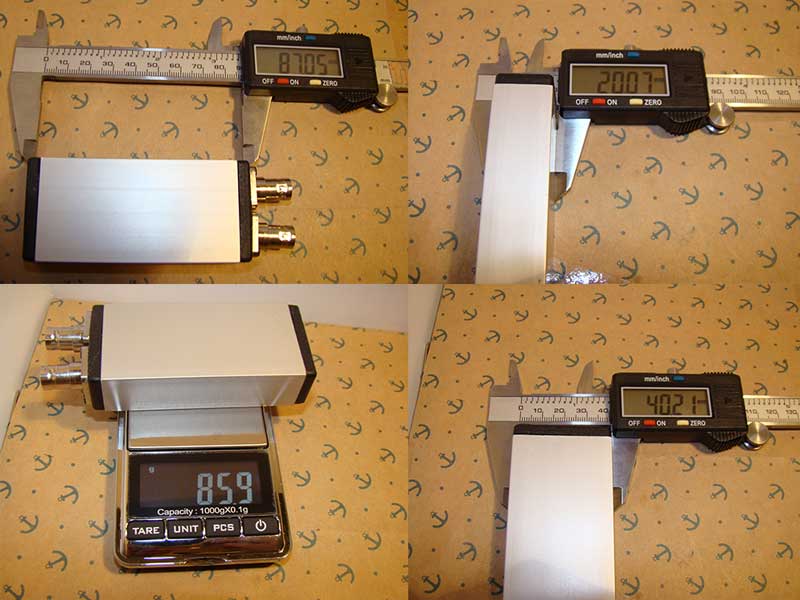
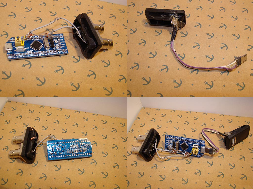
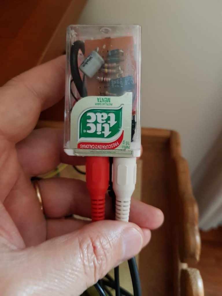
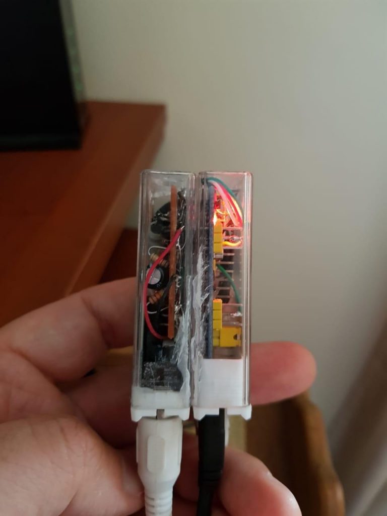
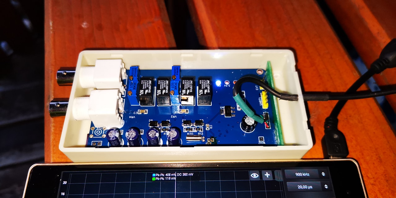
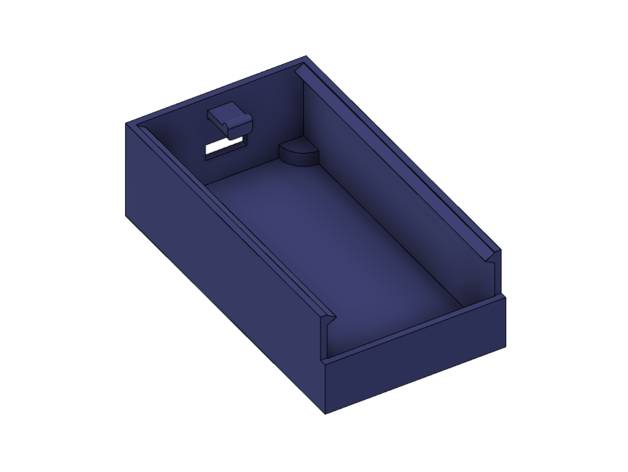
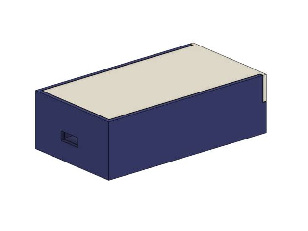
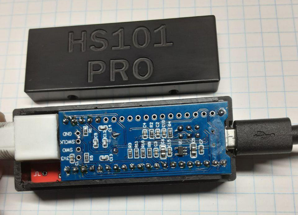
Schematics & Built
Resources

Notes
Flash the Firmware
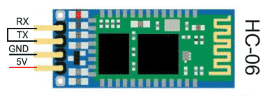
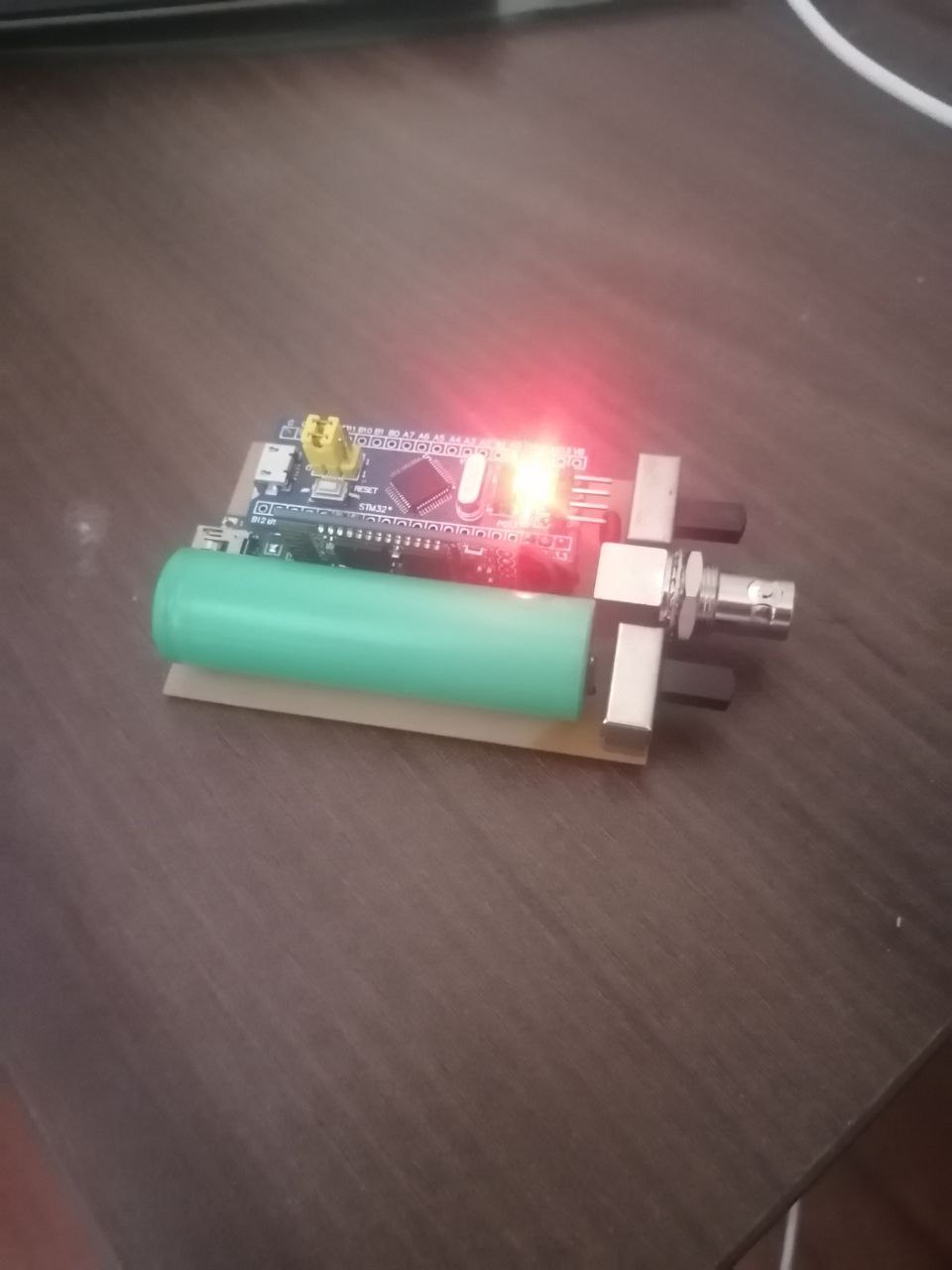
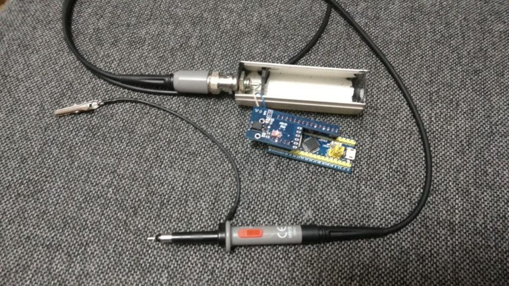
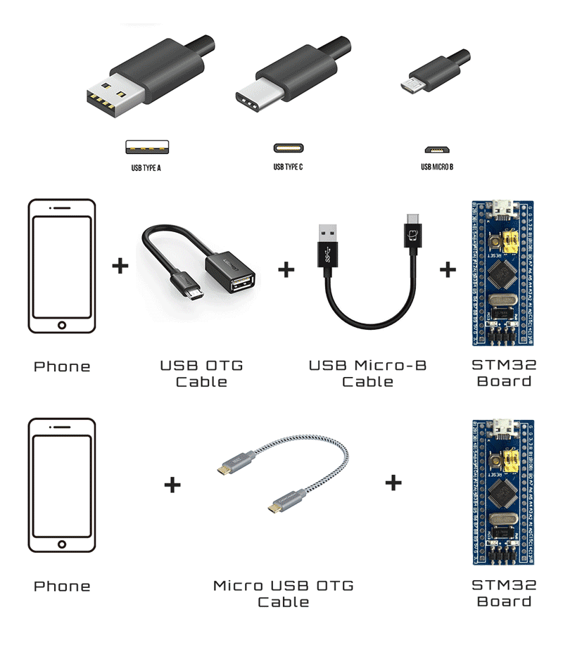
The firmware flashing is made with the app STM32 Utils with an OTG adapter connected to the phone and an USB-TLL adapter connected to the OTG adapter. After connecting the phone to the STM32 Black Pill board like in picture, the red led light up.
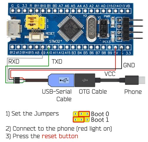
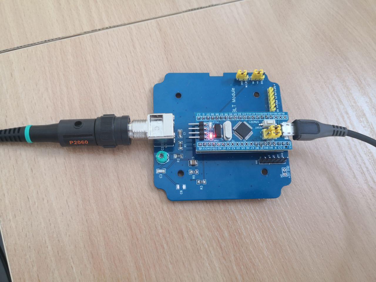
By setting the jumpers on the Blue Pill as in picture, the board enter into the STM boot loader and it is ready to be flashed. On the App:
1) Go to Init Chipset and check that the app read the chipset
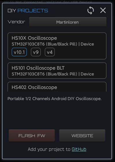
2) Go to the Blue Box icon and in the list under vendor Martinloren select HS10X Oscilloscope, then FLASH FW.
3) After flashing disconnect the USB-TTL cable from the STM32 board, put the jumpers in original position (see picture) and connect the STM32 to the phone through the OTG cable. Open HScope, the app should show you the signal from Channel 1.
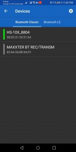
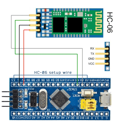
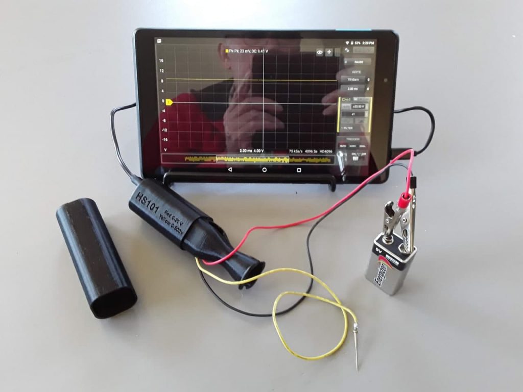
Connection
First Setup / Calibration
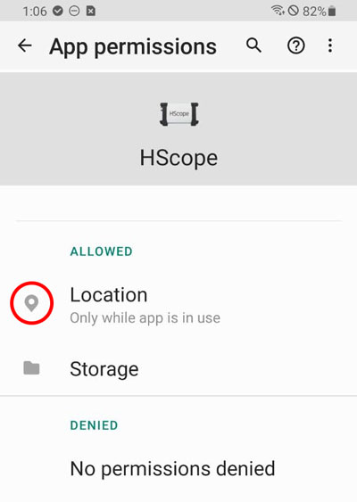
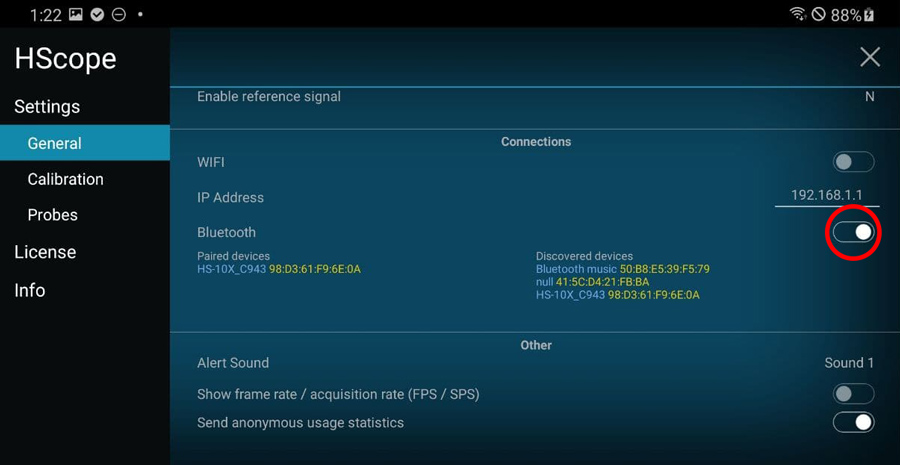
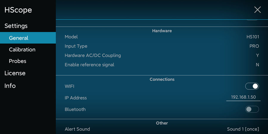
When the oscilloscope is connected go in HScope Settings, General - Hardware. Here:
- Set the Model to
HS101and Input Type toPRO. When you do this change also the option Hardware AC/DC Coupling will be enabled automatically. - Disconnect and reconnect the oscilloscope to get the new configurations.
Offset Calibration
- (required just for Hardware Option 1) Connect Channel 1 probe to its GND.
- For Channel 1 do the Calib Zero Lvl procedure in the
Settings -> Calibration.
Frequency Calibration
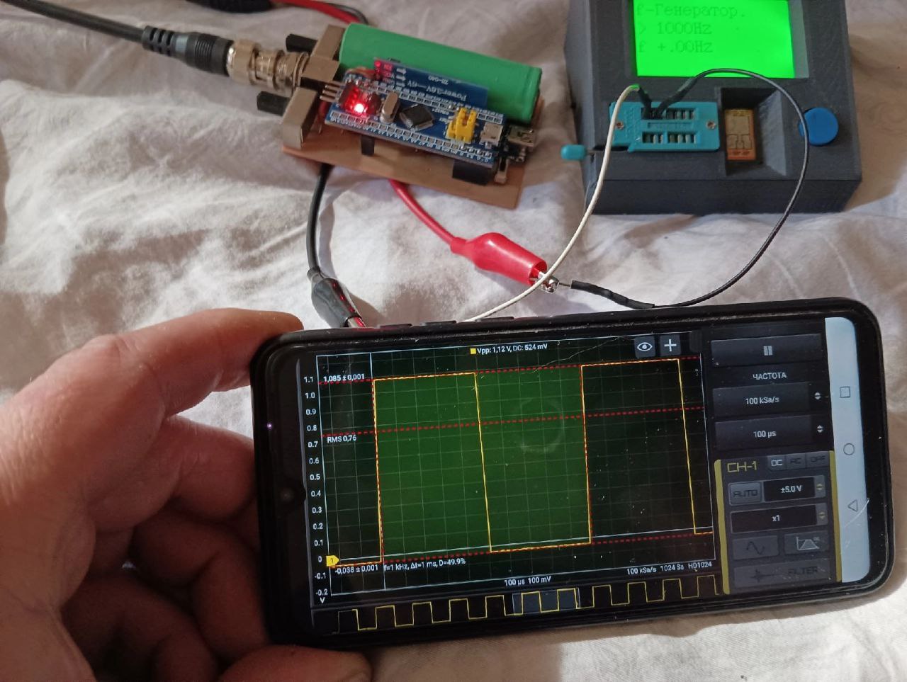
- Enable the PWM signal using the PWM module (red square icon in the right menu, then open the module). HS101 will generate a square wave on pin
B8(1kHz initially). - Connect the probe to pin
B8. Use an high rate, i.e. 450KSa/s and turn the variable capacitor until the rising part of the square wave reproduce a good square. Do this for each channel.
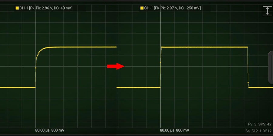
Now the device is calibrated in frequency response.
Multiplier Calibration
For this calibration you need an accurate voltage source, for example 3.3V or 5V from a voltage stabilizer. 5V from USB port is not accurate and should never be used for this calibration. Batteries also should not be used. At least you can use LM7805 or this kind of linear voltage regulators.
- For each channel do the Calib Multiplier procedure in the
Settings -> Calibration.
HW Debugging
Here the tests you can perform in case of issues:
- Check that
PGNDis approximately around 1.65V respect GND.A0pin (analog input) also should be at the same voltage with no input signal is applied. - With a multimeter check that there are no shortcuts among the pins
B4, B5, B6, B7(these are connected to the PGA (U1) which are very small and are easy to get shortcuts between the pins). - To check that the AC/DC coupling works just apply a battery to the input. When DC is selected you should read the voltage of the battery, when AC is selected you should read 0V.
Additional Resources
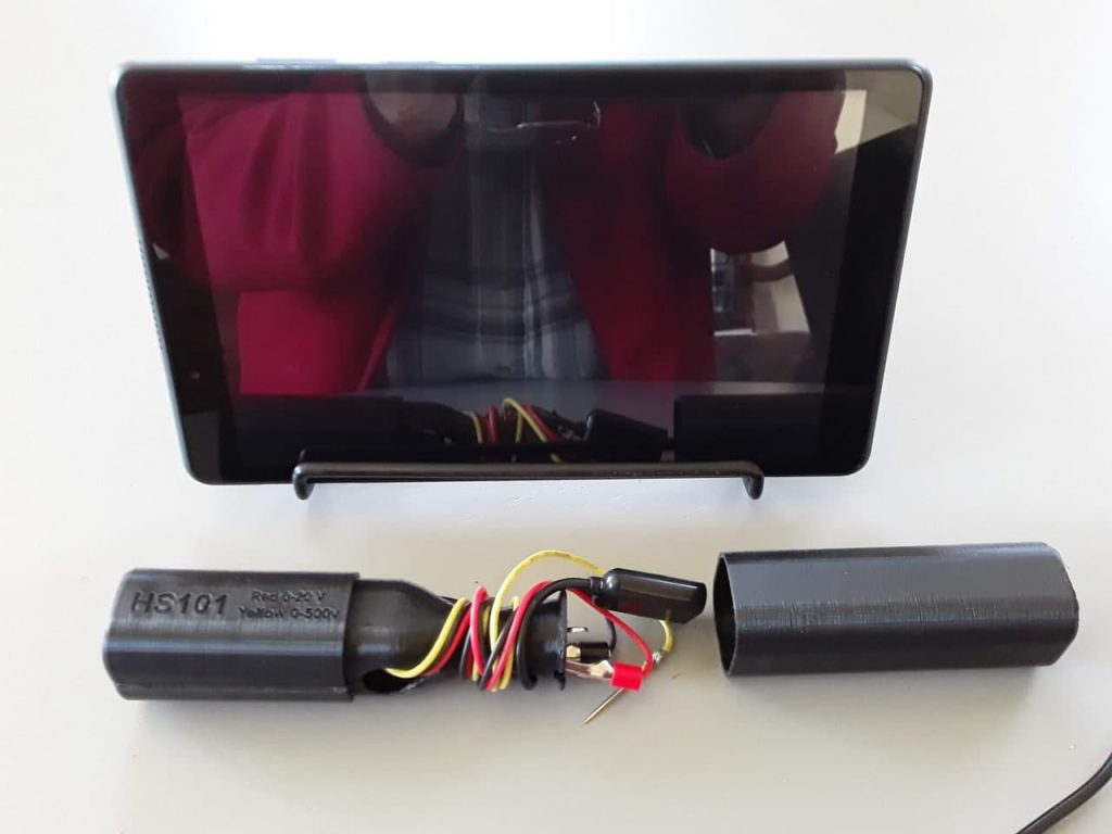
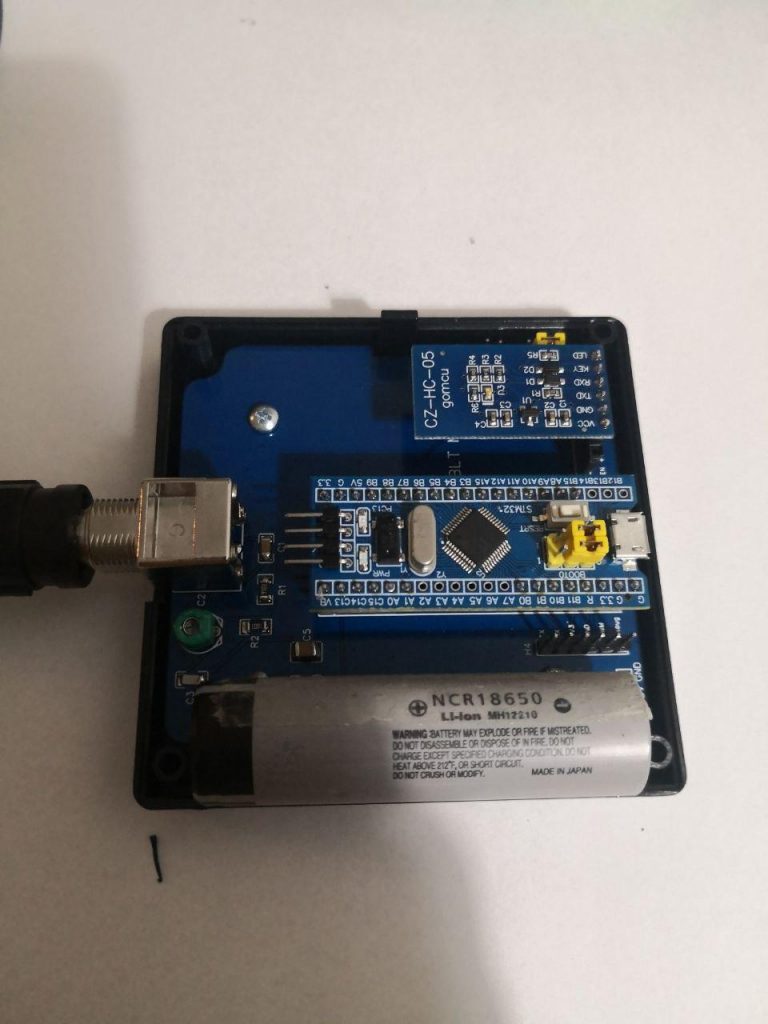
Components info (by Denis)
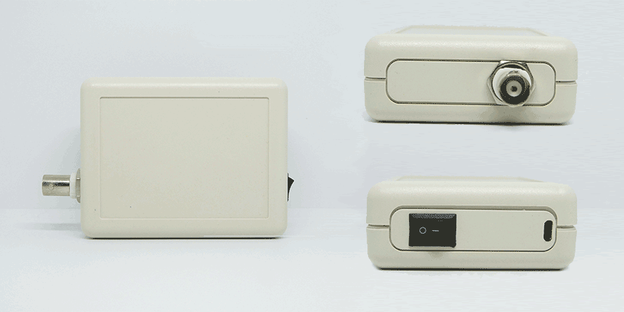
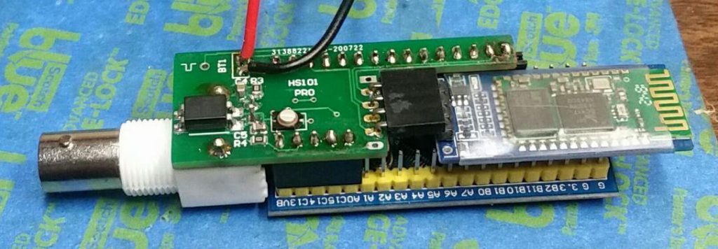
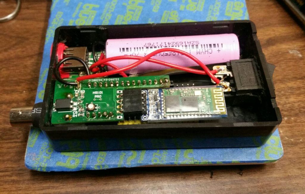
Bluetooth COP Probe with HS101 PRO (by Denis)
First Release: May 2018
Last Update: Dec 2020