
HS402 – Building Instructions
What do you need
- STM32F411 Development Board (Black Pill)
- USB-TTL adapter to flash the STM32 (or ST-LINK in alternative)
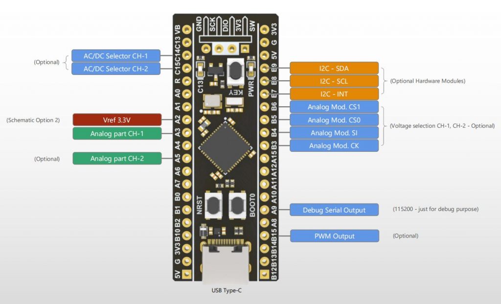
- HS402 PCB with all its components (or custom circuit for the analog part)
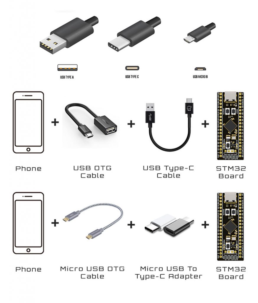
- USB OTG cable for the phone (examples provided following)
Quick Video Instructions
Article link.
Schematics & Built


Notes
- Other STM32F411 development boards can be used, the important is that the main crystal is 25MHz
- On the schematic are indicated 2 or 3 hardware options. One exclude the other.
Flash the Firmware
The firmware flashing is made with the app STM32 Utils with an OTG adapter connected to the phone and an USB-TLL adapter connected to the OTG adapter. After connecting the phone to the STM32 Black Pill board like in picture, the red led light up.
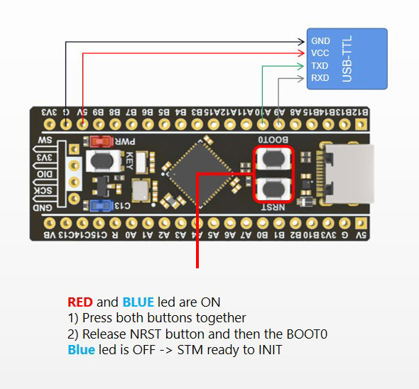
By pressing the buttons on the Black Pill as in picture, the board enter into the STM boot loader and it is ready to be flashed. On the App:
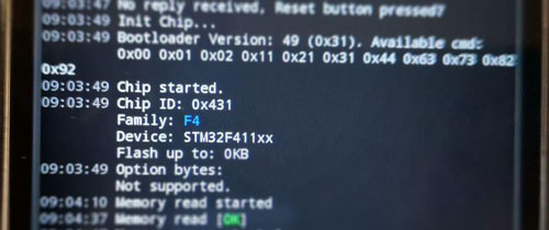
1) Go to Init Chipset and check that the app read the chipset
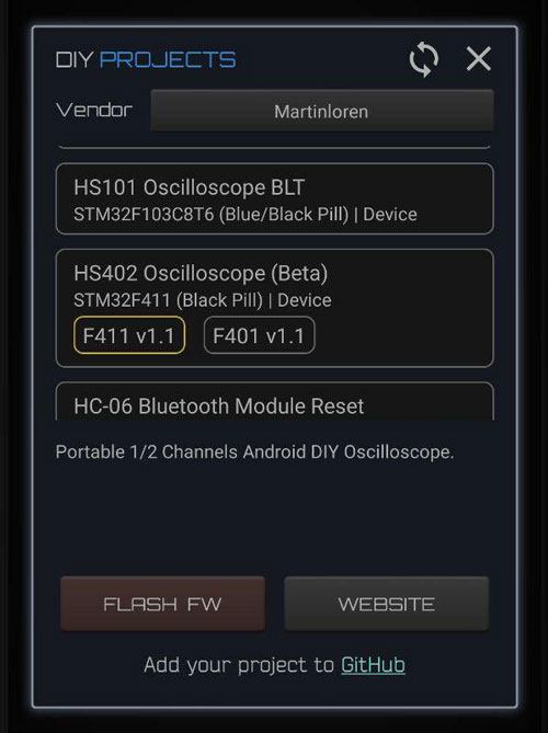
2) Go to the Blue Box icon and in the list under vendor Martinloren select HS402 Oscilloscope, select the chipset from the variants (STM32F411 or STM32F401), then FLASH FW.
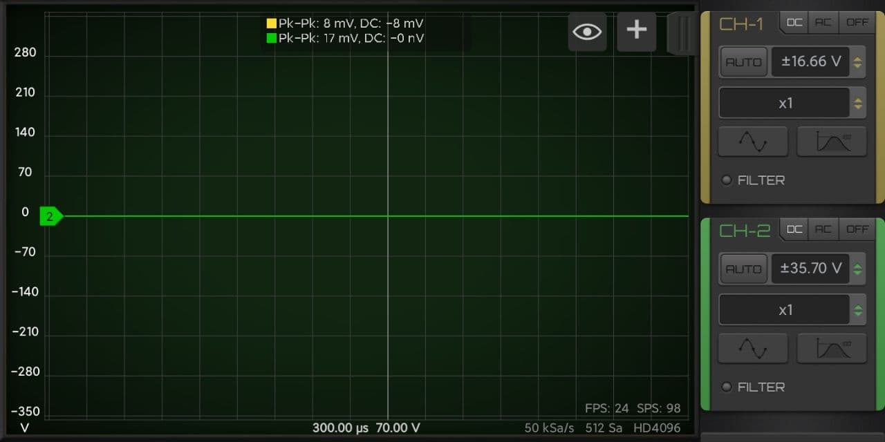
3) After flashing disconnect the USB-TTL cable from the STM32 board and connect the STM32 to the phone through the OTG cable. Open HScope, the app should show you the signal from Channel 1.
Connection
First Setup / Calibration
When the oscilloscope is connected go in HScope Settings, General - Hardware. Here:
- Set the Model to
HS402and Input Type toPRO. When you do this change also the option Hardware AC/DC Coupling will be enabled automatically. - Disconnect and reconnect the oscilloscope to get the new configurations.
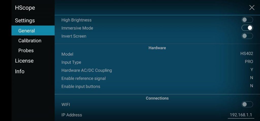
You can also Enable the input buttons if you have installed the corresponding I2C module.
Offset Calibration
- (required just for Hardware Option 1) Connect Channel 1 probe to its GND.
- (required just for Hardware Option 1) Rotate the precision variable resistor (R9) until the software show a DC voltage quite near to 0. This trimmer requires a lot of turns. Make sure with a multimeter that its value is around 1Kohm before proceed with the fine tuning.
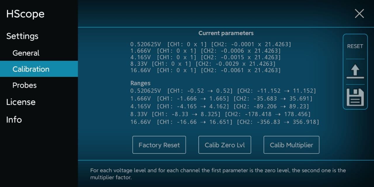
- For each channel do the Calib Zero Lvl procedure in the
Settings -> Calibration.
Frequency Calibration
- Enable the PWM signal using the PWM module (red square icon in the right menu, then open the module). HS402 will generate a square wave on pin
B15(1kHz initially). - Connect the probe to pin
B15. Use an high rate, i.e. 450KSa/s and turn the variable capacitor until the rising part of the square wave reproduce a good square. Do this for each channel.
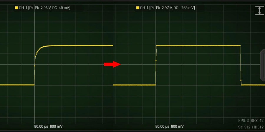
Now the device is calibrated in frequency response.
Multiplier Calibration
For this calibration you need an accurate voltage source, for example 3.3V or 5V from a voltage stabilizer. 5V from USB port is not accurate and should never be used for this calibration. Batteries also should not be used. At least you can use LM7805 or this kind of linear voltage regulators.
- For each channel do the Calib Multiplier procedure in the
Settings -> Calibration.
HW Debugging
Here the tests you can perform in case of issues:
- Check that
PGNDis approximately around 1.65V respect GND. In Option 1 the R9 trimmer requires a lot of turns to get the offset near the 0. With a multimeter you can test it reach around 1Kohm and then fine tune the zero level with HScope.A3andA5pins (analog inputs) also should be at the same voltage with no input signal is applied. - With a multimeter check that there are no shortcuts among the pins
B3, B4, B5, B6(these are connected to the PGA (U1, U3) which are very small and are easy to get shortcuts between the pins). - Check that voltage change on C4 and C5 when on HScope you enable/disable AC/DC option on the channels. To check that the AC/DC coupling works just apply a battery to the input. When DC is selected you should read the voltage of the battery, when AC is selected you should read 0V.
Hardware options
Hardware options in the schematics are meant to give the possibility to the user to have a lower noise by using more components. Higher option number means a better circuit.
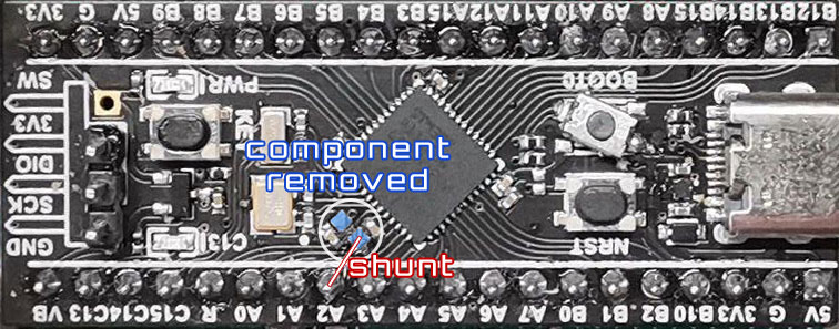
Schematic Option 2 and 3
This option provide a stable reference voltage to the STM32 ADC, by installing the part indicated in the Schematic as Option 2 and 3. It requires also a modification on the STM32 board in order to bring the Vref pin from the STM32 to one of the pins of the development board (PA2). One component should be removed (the inductor) and a jumper should be created to PA2 according the picture under. PA2 is inactive and used just to provide the Vref signal. Demo video here.
Option 2 just show a greater cross-channel noise respect Option 1: 0.25% vs 0.05%.
Note: after this modification the STM32 board will work only if 3.3V is applied to PA2 (now Vref)!
Arbitrary Input Range
You can design the input ranges for each channel according your needs. For example it is possible to have the maximum voltage to ±5V or to ±50V. Channel input ranges can be also different (for example a channel has max voltage ±16V and the other channel ±5V).
- Calculate R2/R3 (or R6/R7) resistors values according the required range. Pay attention the sum of these 2 resistor should be around 1Mohm.
a) R2 + R3 = 1Mohm
b) ±Range = 1.65 * (R2 + R3) / R3
Example: Range = 1.65 * (910k + 100k) / 100k = ±16.66V - Do the multiplier calibration of the channel. After the software will show the voltage ranges according the hardware.
Warning: do not exceed 50V input range since the input is not isulated from GND and from the phone, leading to a possible electrocution.