HS402 – Additional Modules
Hardware Buttons Module
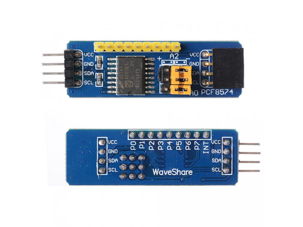
By connecting the PCF8574 I2C module it is possible to have 8 hardware buttons to control the oscilloscope. These are the pin that should be connected to the STM32: GND, VCC (5V), SDA, SCL, INT. Buttons are triggered by connecting the P0-P7 pins to GND. The configuration jumpers on the PCF module should be as in the picture (it use the base address).
Button functions
- P0: Start / Stop
- P1: Rate up
- P2: Rate down
- P3: Fit waveform to screen
- P4-P7: (not assigned)
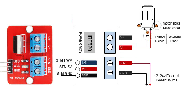
PWM Module
HS402 can generate PWM output. A MOS driver like the MOSFET IRF520 Module Board can be used to control loads. Here the schematic of connections. A video about how to use the HScope PWM module is shown under. The IRF520 has been tested at 1KHz PWM frequency and showed low pass characteristics so it is not suggested to use an higher frequency.