
HS402-WiFi Building Instructions
If you want to go fast I suggest you to check some guide made by other users:
- Full Article for the first video: link
- Project material can be found here in Github, other resources at the end of this page
- It is suggested to join the Telegram group to get more info and support
Hardware
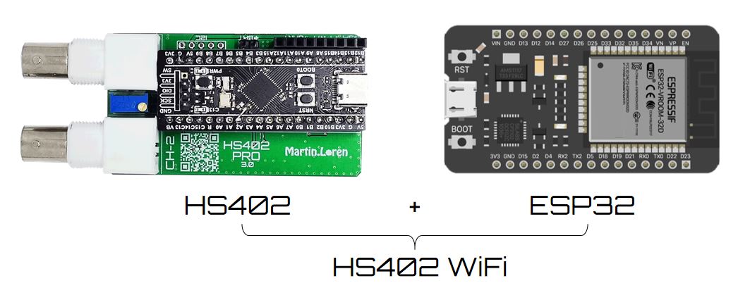
To build the HS402-WiFi oscilloscope you can choose among these 2 options.
1. Easy Built
You need:
- HS402 oscilloscope (built with PCB V2.0 or PCB V3.0) with Firmware ver. ≥ 1.7
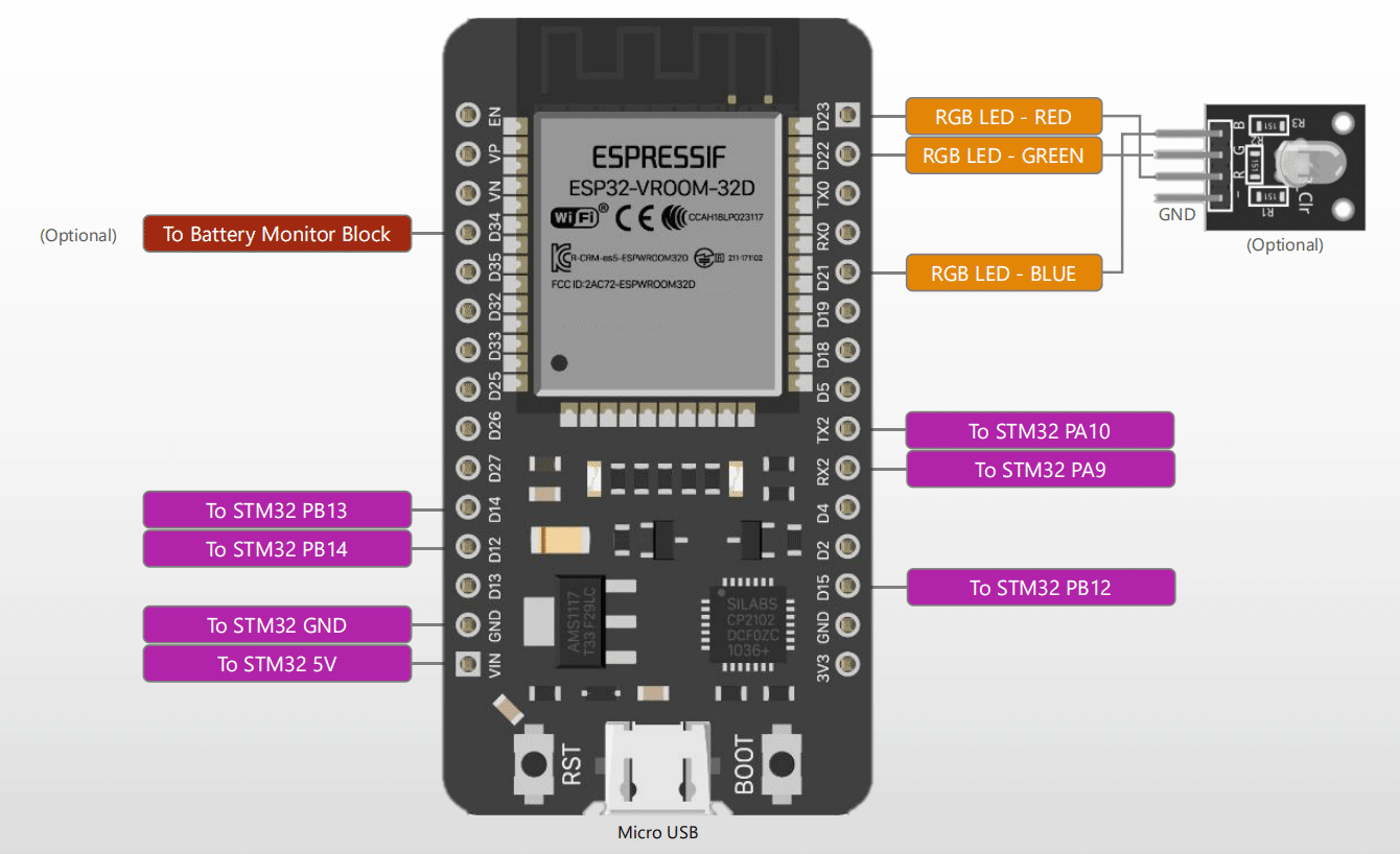
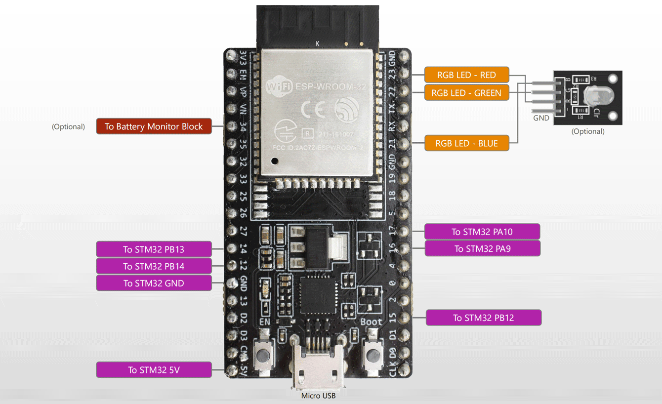
- ESP32 Development board (one with ESP32-WROOM first version or ESP32-WROOM-32D), connected to STM32 as following and flashed with latest ESP32 Firmware. Flashing instructions here.
- You can also use a PCB adapter created by Mikael to connect the ESP32 and STM32 together. Look at this project here, usage video here.
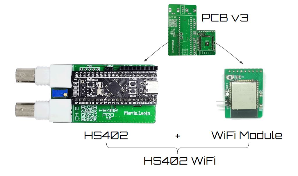
2. Full Built (with PCB v3)
- A compact built using PCB v3 which integrate all the components, including the ESP32-WROOM chip
- PCB v3 is composed by 2 parts that need to be separated. Then main PCB is for the standard HS402 USB oscilloscope, the small PCB is the WiFi Module.
You need:
- Get PCB v3, split the 2 board along the separation line by using a knife on both side and the apply a pression on both side to take the 2 board apart.
- Solder all the components. A demo of the STM installation for PCB v3 is here.
- Flash the STM32 and the ESP32
- Put the WiFi Module over the HS402 long connector (top right)
- Power from BAT connector (3.6 – 5V) or from USB connector of the STM32
After just follow the User Guide to connect the WiFi configuration page.
Firmware / Software
- STM32 with HS402 Firmware ver. ≥ 1.7
- ESP32 with latest Firmware
- HScope Android app ver. ≥ 214
Powering with Battery
1. With 5V Battery Pack
- Possible with whatever hardware built
Just connect a classic phone charger to the USB port of ESP32 or of the STM32 to power up the oscilloscope.
You can also disassemble a phone charger and add a switch for power, as done in this video.
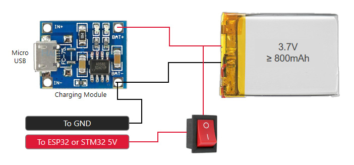
2. With 3.7V Lithium Battery
- Possible only by using the hardware Option 3 in the PCB v3
With the hardware Option 3 in the PCB v3 it is possible to power the oscilloscope directly with a 3.7V Lithium battery. You can add also a micro-charger circuit as in the following schematic. This configuration allow the lower power consumption for this device (around 180mA avg).
Resources
- Open Source Hardware Schematic for HS402-WiFi V3.0 available here.